Transcription of 9. TRANSMISSION OF SOUND THROUGH STRUCTURES
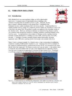
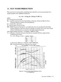
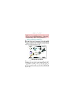
1 NOISE CONTROL TRANSMISSION J. S. Lamancusa Penn State 12/1/2000 9. TRANSMISSION OF SOUND THROUGH STRUCTURES Basic Definitions A typical noise control application involves a combination of absorption of SOUND and TRANSMISSION of SOUND energy by a variety of airborne and stucture-borne paths. Figure 1. SOUND TRANSMISSION paths between a room containing a noise source and adjacent rooms Some important definitions and concepts: TRANSMISSION Coefficient , for walls IncidentdTransmitteII= ( is a frequency-dependent physical property of the material) SOUND TRANSMISSION loss STL = the log ratio of the incident energy to the transmitted energy STL = 10 log 1/ Equation 1 A tabulation of TRANSMISSION loss for common materials is included in the Appendix to this section (from Table , ref Bies and Hansen). A perfectly reflecting material has a TRANSMISSION coefficient of 0 (STL = ), while the TRANSMISSION coefficient of an opening is IIncident IReflected ITransmitted Figure 2.
2 When SOUND strikes a partially absorbing partition between two rooms, some is reflected back into room, some transmits into adjacent room Source Room 1 LP1 Receiver Room 2 LP2 NOISE CONTROL TRANSMISSION J. S. Lamancusa Penn State 12/1/2000 (STL=0). It should be noted that typical materials tend to be better at blocking higher frequencies. TRANSMISSION loss can be measured directly (but not easily) by mounting a test panel between two reverberation rooms and measuring the SOUND pressure levels on each side. Other commonly used metrics to describe SOUND TRANSMISSION include: NR = Noise Reduction = LP1-LP2 (easy to measure) Note: NR STL ! IL = Insertion loss = change in SOUND levels with and without the barrier or treatment in place (easy to measure) Relation Between LP1 and LP2 The SOUND power incident on the left side of the wall is, (assuming a diffuse SOUND field): W1 = I1 SW SW = Area of the common wall I1 = Intensity incident on wall I2 = Intensity transmitted to room 2 and since I1 = the intensity in a plane wave, the SOUND power striking the left side of the wall is: WWScpSIW 42111 == In the receiving room (Room 2), we know that whatever power comes THROUGH the common wall, must eventually be absorbed in that room.
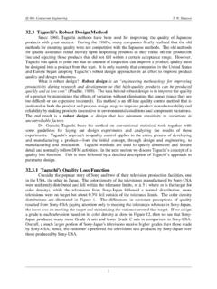
3 We will call the power coming THROUGH the wall W2: W2 = I2 S2 2 where S2 = total surface area of receiving room 2 = room average absorption for receiving room and assuming a diffuse field in receiving room, I2 = <p22>S2 2/(4 c) Using the definition of : WSpSpWWII2122221212 === Take the log and rearrange: 22102222211010log10log101log10 SSppppSTLWREFREF+= = or more simply: 221021log10 SSLLSTLWPP+ = Equation 2 Now we have a very useful expression that will tell us the SOUND level in the receiver room 2. ROOM 1 ROOM 2 LP1 LP2 I1 I2 Figure 3. SOUND TRANSMISSION between two rooms, the area of the common wall = SW NOISE SOURCE, W NOISE CONTROL TRANSMISSION J. S. Lamancusa Penn State 12/1/2000 SOUND Levels in Source Room Meanwhile, back in the noise source room, Room 1: ++=RrQLLWP4 4log102101 STSTSR =1 If we neglect the direct field portion, (ok approximation if room is not too absorptive and you are far from the noise sources), then: RLLWP4log10101+= Substituting into equation 2: 2221010log104log10 PWWLSTLSSRL= ++ Equation 3 Look at trends to see if this equation makes physical sense: LP2 decreases if R increases (more absorption in room 1) if STL increases (more TRANSMISSION loss , a better wall) if 2 increases (more absorption in room 2) if Sw decreases (less common area, transmitted power is proportional to Intensity striking the wall times wall area) HW Problem 1.
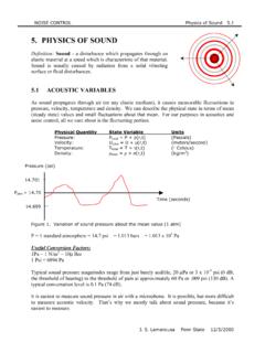
4 In addition to a barrier material, an absorbing layer (a=.90) is to be used on the wall between a source room and a receiver room. The barrier material has an absorption coefficient of a=.10. The TL of the composite wall is 43. Each room is a 5 meter cube. What is the difference between placing the absorbing layer on the source side versus the receiver side of the wall? (answer: each case results in the same levels in room 2, however putting it on the inside also decreases the level inside room 1) Noise Enclosures An enclosure around a noise source is just a special case of the two room problem, where the enclosure is one room, and the surrounding space is the second room (Figure 4). It can be shown that the insertion loss for this case is: log10'22 =PPLLIL Equation 4 Where: LP2 = SPL without enclosure LP2= SPL with enclosure = effective absorption coefficient within enclosure = effective TRANSMISSION coefficient of enclosure walls Figure 4.
5 Enclosure around a noise source LP2 enclosure NOISE CONTROL TRANSMISSION J. S. Lamancusa Penn State 12/1/2000 Problem 2: Verify equation 4. List all assumptions that are made in the derivation Problem 3: A 1x1x1 meter enclosure is placed around a noise source in a 5x5x5meter room. In addition to a barrier material, an absorbing layer ( =.90) is used on the walls of the enclosure. The TL of the composite wall is 43. The barrier material has an absorption coefficient of =.10. Should the absorbing layer be on the outside or inside surface of the enclosure for maximum effect? (answer: putting it on the inside results in 8 dB lower levels in room) What is the difference between an absorbing material and a barrier material? The two important noise-related quantities of a material are: Ability to absorb acoustic energy - Ability to reflect or block SOUND energy - STL or Good absorbing materials allow SOUND pressure fluctuations to enter their surface and dissipate energy by air friction.
6 The are generally porous and lightweight, such as fiberglass, open cell foam, or acoustical ceiling tiles. Good barrier materials reflect SOUND , and are dense and non-porous (concrete, lead, steel, brick,glass, gypsum board). In general, a single homogeneous material will not be both a good absorber and a barrier. As shown in Table 1, fiberglass insulation makes a terrible barrier, and a sealed concrete wall has virtually no absorption. To get the best of both worlds, it is common to see an absorbing layer laminated to a barrier material, for instance a layer of gypsum board and a layer of fiberglass, or loaded vinyl laminated to open cell foam. Table 1. Comparison of various material noise properties at 1000 Hz Material Absorption TRANSMISSION Concrete Cinder Block (painted) .07 very low .0001 (STL=40) high 2 Fiberglass.
7 90 high ~ very low NOISE CONTROL TRANSMISSION J. S. Lamancusa Penn State 12/1/2000 SOUND TRANSMISSION Class SOUND TRANSMISSION Class (STC) is a single number rating of TRANSMISSION loss which is popular with architects. It is obtained by fitting the closest standard contour to the actual TL vs frequency data for the material (see Figure 5, ref Bies and Hansen). The STC is determined by comparing the set of TRANSMISSION losses at all 16 1/3 octave center frequencies to a set of standard contours as described in ASTM Standard E413-70T. The TL curve must fit the standard contour in such a way that in no event is the TL curve more than 8 dB below the STC contour at any frequency, and the sum of the deviations of the TL values which are below the contour shall not exceed 32 dB. The highest contour to which the specimen TL curve can satisfy these requirements is used as the STC curve.
8 Table 2 relates STC with the hearing quality. The STC of various composite frame wall constructions is shown in Figure in the Appendix. The standard STC contours are shown in Table 3. Figure 5. STC rating is determined by adjusting the standard contours to the measured TL values and reading the contour intercept at 500 Hz. NOISE CONTROL TRANSMISSION J. S. Lamancusa Penn State 12/1/2000 Table 2. Typical hearing quality for a wall of rated SOUND TRANSMISSION class (STC) SOUND TRANSMISSION Class (STC) Hearing Quality THROUGH Wall 25 Normal speech understood quite easily and distinctly THROUGH wall 30 Loud speech understood fairly well, normal speech heard but not understood 35 Loud speech heard but not intelligible 40 Onset of privacy 42 Loud speech audible as a murmur 45 Loud speech not audible, 90% of statistical population not annoyed 50 Very loud sounds such as musical instruments or a stereo can be faintly heard, 99% of population not annoyed Table 3.
9 Standard STC contours (note: a particular contour is identified by its TL value at 500 Hz) from ASTM E413 NOISE CONTROL TRANSMISSION J. S. Lamancusa Penn State 12/1/2000 Multi-Layer Panels - Constructions for High STC Examples of multiple layer constructions to achieve high STC are shown in the following figures. The fundamental principles are to minimize any direct mechanical connection between the two surfaces of the wall, and to have no openings or leaks. Problem areas for leaks are air vents, around doors, electrical outlets or pipe penetrations. NOISE CONTROL TRANSMISSION J. S. Lamancusa Penn State 12/1/2000 Figure 6 Construction details of frame walls for high STC (courtesy of Owens Corning) Similar considerations apply to floors and ceilings.
10 Additionally, floors are rated by their Impact Insulation Class, (IIC). Resilient layers, or carpet are used to insulate the TRANSMISSION of impact noise (such as footsteps). Layered floor constructions are shown in Figure 7. NOISE CONTROL TRANSMISSION J. S. Lamancusa Penn State 12/1/2000 Figure 7 Construction details for floor and ceiling systems that control impact SOUND (Courtesy of Owens Corning)NOISE CONTROL TRANSMISSION J. S. Lamancusa Penn State 12/1/2000 Composite Walls If a wall or partition is not of uniform construction, its effective TRANSMISSION loss can be determined by summing over the n different surfaces in the same manner that we determined a room-averaged absorption coefficient: ===niiiniicompositeSS11 Equation 5 where i = TRANSMISSION coefficient of ith surface, having area Si Example: a wall with door and window Surface Area STL Door 3 x 7 =21 ft2 20.