Transcription of 90HBW˜ Thru-Hole DIP Switches SERIES 78 …
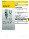
1 Grayhill, Inc. 561 Hillgrove Avenue LaGrange, Illinois 60525-5997 USA Phone: 708-354-1040 Fax: 708-354-2820 DIP SwitchesDIP SwitchesSERIES 78 SPST To 4 PST Slide OPEN CLOSEDS eries 90 HBW 90B 76 78 FEATURES Raised and Recessed Slides SPST, 2 PST, 3 PST, 4 PST Sealed Base Standard Spring and Ball Contact Top Tape Seal Option2134O N2134O N Single Pole/Single Throw SwitchCIRCUITRYFor Switches with 5, 6, 7, 8, or 10 PST circuitry, contact Multiple Pole SwitchTypical Circuit Diagram1O N1O N No. of Length Length Raised Recessed Circuitry Positions Inches Metric Tube Slides* Slides* 2 " 7,1mm 35 78B02T 78RB02T 3 " 9,7mm 27 78B03T 78RB03T 4 " 12,2mm 21 78B04T 78RB04T 5 " 14,7mm 18 78B05T 78RB05T SPST 6 " 17,3mm 15 78B06T 78RB06T 7 " 19.
2 8mm 13 78B07T 78RB07T 8 " 22,4mm 12 78B08T 78RB08T 9 " 24,9mm 10 78B09T 78RB09T 10 " 27,4mm 9 78B10T 78RB10T 12 " 32,5mm 8 78B12T 78RB12TT 1 " 7,1mm 35 78F01T 2 " 12,2mm 21 78F02T 2 PST 3 " 17,3mm 15 78F03T 4 " 22,4mm 12 78F04T Recessed 5 " 27,4mm 9 78F05T Slides 6 " 32,5mm 8 78F06T Not Available 1 " 9,7mm 27 78G01T 3 PST 2 " 17,3mm 15 78G02T 3 " 24,9mm 10 78G03T 4 PST 1 " 12,2mm 21 78H01T 2 " 22,4mm 12 78H02 TORDERING INFORMATION Single Pole/Single Throw Switch in Raised and Recessed SlidesDIMENSIONS In inches (and millimeters)Note.
3 Recessed slides have a dimple for tool actuation. For recessed slides, the .295 dimension does not Pole/Single Throw and Typical Multiple Pole Switch with Raised .010(9,65 0,25)SEE ORDERINGINFORMATIONCLCLDIM. B .002( 0,05).020 .002 (0,51 0,05).090 .005 (2,29 0,13).100 .005 (2,54 0,13)2 PST = .100 (2,543 PST = .200 (5,08)4 PST = .300 (7,62)= .010(9,65 0,25)SEE .002 (1,52 0,05).020 .002 (0,51 0,05).090 .005 (2,29 0,13).100 .005 (2,54 0,13)C LC (1,78) + .000 .020 (7,49 0,51).020 .002 (0,51 0,05).156 + .015 .010 (3,96 + 0,38 0,25) = .245 + .000 .020 (6,22 + 0,51).)
4 050 .005 (1,27 0,13) .010 (4,57 0,25).012 .001 (0,30 0,03).300 + .030 .000 (7,62 + 0,76)*A top tape seal is required for Switches that are machine soldered or heavily cleaned after hand soldering. To order top seal versions, add "S" to the Grayhill part from your local Grayhill prices and discounts, contact a local Sales Office, an authorized local Distributor or ORDERINGINFORMATIONG rayhill, Inc. 561 Hillgrove Avenue LaGrange, Illinois 60525-5997 USA Phone: 708-354-1040 Fax: 708-354-2820 DIP SwitchesDIP SwitchesRatings 76 78 90 BMechanical Life: Operations per switch position 2,000 2,000 2,000 Make-and-break Current Rating: Operationsper switch position at these resistive loads1 mA, 5 Vdc; 50 mA, 30 Vdc; or 150 mA, 30 Vdc: 2,000 2,000 10 mA, 30 Vdc; or 10 mA, 50 mVdc: 2,00010 mA, 50 mVdc; or 25 mA, 24 Vdc.
5 Or 100 mA, 6 Vdc: 2,000 Contact Resistance: Initially: 30 m 30 m 20 m After life, at 10 mA, 50 mVdc, open circuit: 100 m 100 m 100 m Insulation Resistance:Minimum, at 100 Vdc between adjacent closedcontacts and also across open switch contacts Initially (Mohms): 5,000 5,000 5,000 After life (Mohms): 1,000 1,000 1,000 Dielectric Strength: Minimum voltage (AC,RMS) measured between adjacent closedcontacts and also across open switch contacts. Initially: 750 V 750 V 500 V After life: 500 V 500 V 500 VCurrent Carry Rating: Maximum rise of 20 C 5 A 4 A 3 ASwitch Capacitance: At 1 megahertz 2 pF 2 pF 2 pFOperating Temperature Range: -40 C to + 85 C -40 C to + 85 C -40 C to + 85 CStorage Temperature Range: -55 C to + 85 C -55 C to + 85 C -55 C to + 85 CSPECIFICATIONS: Standard StylesMechanical RatingsVibration Resistance: Per Method 204, Test Condition B, 1 mS opening (10 mS allowed)Mechanical Shock: Per Method 213, Test Condition A.
6 1 mS opening (10 mS allowed)Thermal Shock Resistance: Per specification; no failures; passes contact Strength: Per specificationThermal Aging: 1,000 hours at 85 C; no RatingsMeets all requirements of MIL- S-83504. Where Grayhill performance is superior, the MIL spec is listed in Resistance: Per specification, Method InformationSeries 90 MIDIP and SERIES 76 recessed rocker (76 RSB style) sealed Switches have been tested to EIA Standard RS-448-2. Similar performance can be expected from other sealed SERIES 76 and 78 DIP : Per MIL-STD-202, Method 208 Resistance to Soldering Heat: 76 RSB: Passes EIA Standard using two, four, and six second soldering time.
7 90: Per MIL-S-83504, six second : Per EIA RS-448-2 with flux touching switch : 76, 78 and 90 SERIES tape sealed products: Passes immersion test using water/detergent. Acceptable solutionsinclude 1-1-1 trichlorethane, freon, (TF, TE, or TMS), isopropyl alcohol, detergent (140 F maximum). Terpene acceptable for SERIES 90 only. Solutions which are not recommended include acetone, methylene chloride, freon and FinishesShorting Member (Ball): Brass, gold-plated 10 microinches minimum over nickel Contacts: Copper alloy, gold-plated over nickel : Copper alloy, matte-tin plated over nickel Parts: Thermoplastic (UL94V-O)Potting Material: Epoxy, 76,78 Cover: 76,78, and Reel PackagingTape Seal:76, 78: Polyester film90: Polyimide filmTape Seal Integrity: Passes gross leak test using 125 C flourinert for 20 seconds minimum.
8 Reference MIL-STD-202, Method 112.