Transcription of 98000160100 Rev D FLEXmax Spec Sheet[1]
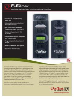
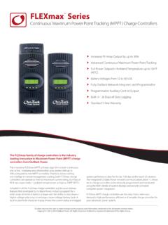
1 Increases PV Array Output by up to 30% Advanced Continuous Maximum Power Point Tracking Full Power Output in Ambient Temperatures up to 104 F (40 C) Battery Voltages from 12 VDC to 60 VDC Fully OutBack Network Integrated and Programmable Programmable Auxiliary Control Output Built-in 128 days of Data Logging Standard 5 Year WarrantyContinuous Maximum Power Point Tracking Charge ControllersThe FLEXmax family of charge controllers is the latest innovation in Maximum Power Point Tracking (MPPT ) charge controllers from OutBack Power Technologies. The innovative FLEXmax MPPT software algorithm is both continuous and active, increasing your photovoltaic array power yield up to 30% compared to non-MPPT controllers.
2 Thanks to active cooling and intelligent thermal management cooling, both FLEXmax charge controllers can operate at their full maximum current rating, 60 Amps or 80 Amps respectively, in ambient temperatures as high as 104 F (40 C).Included in all of the FLEXmax Charge Controllers are the revolutionary features first developed by OutBack Power, including support for a wide range of nominal battery voltages and the ability to step-down a higher voltage solar array to recharge a lower voltage battery bank. A built-in, backlit 80 character display shows the current status and logged system performance data for the last 128 days at the touch of a button.
3 The integrated OutBack network communications allows FLEXmax series Charge Controllers to be remotely programmed and monitored via a MATE system display and provides unrivaled complete system MPPT Charge Controllers are the only choice when you demand a high performance, efficient and versatile charge controller for your advanced power From: maxTM60 maxTM80 Nominal Battery Voltages 12, 24, 36, 48, or 60 VDC (Single model - selectable via fi eld programming at start-up)Maximum Output Current 80 amps @ 104 F (40 C) with adjustable current limitMaximum Solar Array STC Nameplate 12 VDC systems 1250 Watts / 24 VDC systems 2500 Watts / 48 VDC systems 5000 Watts / 60 VDC Systems 6250 WattsNEC Recommended Solar Array STC Nameplate 12 VDC systems 1000 Watts / 24 VDC systems 2000 Watts / 48 VDC systems 4000 Watts / 60 VDC Systems 5000 WattsPV Open Circuit Voltage (VOC)
4 150 VDC absolute maximum coldest conditions / 145 VDC start-up and operating maximumStandby Power Consumption Less than 1 Watt typicalPower Conversion Effi ciency @ 80 Amps in a 48 VDC System - TypicalCharging Regulation Five Stages: Bulk, Absorption, Float, Silent and EqualizationVoltage Regulation Set points 10 to 60 VDC user adjustable with password protectionEqualization Charging Programmable Voltage Setpoint and Duration - Automatic Termination when completedBattery Temperature Compensation Automatic with optional RTS installed / mV per C per 2V battery cellVoltage Step-Down Capability Can charge a lower voltage battery from a higher voltage PV array - Max 150 VDC inputProgrammable Auxilary Control Output 12 VDC output signal which can be programmed for diff erent control applications (Maximum of amps DC)Status Display (8 cm)
5 Backlit LCD screen - 4 lines with 80 alphanumeric characters totalRemote Display and controller Optional Mate or Mate2 with RS232 Serial Communications PortNetwork Cabeling Proprietary network system using RJ 45 Modular Connectors with CAT 5e Cable (8 wires)Data Logging Last 128 days of Operation - Amp Hours, Watt Hours, Time in Float , Peak Watts, Amps, Solar Array Voltage, Max Battery Voltage Min Battery Voltage and Absorb for each day along with total Accumulated Amp Hours, and kW Hours of productionHydro Turbine Applications Consult factory for approved TurbinesPositive Ground Applications Requires two Pole Breakers for switching both positive and Negative Conductors on both Solar Array and Battery Connections (HUB 4 and HUB 10 can not be used for use in positive ground applications)
6 Operating Temperature Range Minimum -40 to maximum 60 C (Power capacity of the controller is automatically derated when operated above 40 C)Environmental Rating Indoor Type 1 Conduit Knockouts One 1 (35mm)on the back; One1 (35mm) on the left side; Two 1 (35mm) on the bottomWarranty Standard 5 year / Available 10 YearWeight - Unit lbs ( kg) - Shipping lbs ( kg)Dimensions - Unit (H x W x D) x x ( x 14 x 10 cm) - Shipping 21 x x (53 x 27 x 27 cm) Options Remote Temperature Sensor (RTS), HUB 4, HUB 10, MATE, MATE 2 Menu Languages English & SpanishCertifi cations ETL Listed to UL1741, CSA No.
7 , 24, 36, 48, or 60 VDC (Single model - selectable viafi eld programming at start-up)60 amps @ 104 F (40 C) with adjustable current limit12 VDC systems 900 Watts / 24 VDC systems 1800 Watts / 48 VDC systems 3600 Watts / 60 VDC Systems 4500 Watts12 VDC systems 750 Watts / 24 VDC systems 1500 Watts /48 VDC systems 3000 Watts / 60 VDC Systems 3750 Watts150 VDC absolute maximum coldest conditions / 145 VDC start-up and operating maximumLess than 1 Watt @ 60 Amps in at 48 VDC System voltage - TypicalFive Stages: Bulk, Absorption, Float, Silent and Equalization10 to 60 VDC user adjustable with password protectionProgrammable Voltage Setpoint and Duration - Automatic Termination when completedAutomatic with optional RTS installed / mV per C per 2V battery cellCan charge a lower voltage battery from a higher voltage PV array - Max 150 VDC input12 VDC output signal which can be programmed for diff erentcontrol applications (Maximum of amps DC) (8 cm)
8 Backlit LCD screen - 4 lines with 80 alphanumeric characters totalOptional Mate or Mate2 with RS232 Serial Communications PortProprietary network system using RJ 45 Modular Connectors with CAT 5e Cable (8 wires)Last 128 days of Operation - Amp Hours, Watt Hours, Time in Float , Peak Watts, Amps, Solar Array Voltage, Max Battery Voltage Min Battery Voltage and Absorb for eachday along with total Accumulated Amp Hours,and kW Hours of productionConsult factory for approved TurbinesRequires two Pole Breakers for switching both positive and Negative Conductors on both Solar Arrayand Battery Connections (HUB 4 and HUB 10 can not be usedfor use in positive ground applications)Minimum -40 to maximum 60 C (Power capacity of thecontroller is automatically derated when operated above 40 C)Indoor Type 1 One 1 (35mm)on the back.
9 One1 (35mm) on the left side; Two 1 (35mm) on the bottomStandard 5 year / Available 10 lbs ( kg) lbs ( kg) x x (40 x 14 x 10 cm)18 x 11 x 8 (46 x 30 x 20 cm) Remote Temperature Sensor (RTS), HUB 4, HUB 10, MATE, MATE 2 English & SpanishETL Listed to UL1741, CSA No. Specifi cations- FM80-150 VDC- FM60-150 VDC980-0016-01-00 REV D*Specifi cations subject to change without noticeMain Offi ce:5917 195th St. NE, #7 Arlington, WA 98223 USAP hone: (360) : (360) Offi ce:BARCELONA, Espa aPhone: +