Transcription of 990-1062A REV02 eng - - APC USA
1 990- 1062a 11/01 User s Manual EnglishAPC Smart-UPS 1000VA/1500VA 230 VAC/120 VAC/100 VAC 750XL/1000XL 230 VAC/120 VAC Tower Uninterruptible Power Supply 1 Introduction American Power Conversion Corporation (APC) is the leading national and international manufac-turer of state-of-the-art uninterruptible power supplies, redundant switches , power management soft-ware, and related equipment. APC products protect hardware, software, and data from power distur-bances in business and government offices throughout the world. The APC Uninterruptible Power Supply (UPS) is designed to prevent blackouts, brownouts, sags, and surges from reaching your computer and other valuable electronic equipment. The UPS filters small utility line fluctuations and isolates your equipment from large disturbances by internally dis-connecting from the utility line.
2 The UPS provides continuous power from its internal battery until the utility line returns to safe levels or the battery is discharged. 1: INSTALLATION Read the Safety Instruction sheet before installing the UPS. Unpacking Inspect the UPS upon receipt. APC designed robust packaging for your product. However, accidents and damage may occur during shipment. Notify the carrier and dealer if there is damage. The packaging is recyclable; save it for reuse or dispose of it properly. Check the package contents. The package contains the UPS, a literature kit containing one CD, one serial cable, one USB cable, product documentation and Safety Information. 230V models: Two IEC jumper cables are included and a utility connector plug is included for use on servers with permanently attached power cords.
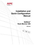
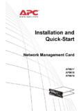
3 The UPS is shipped with the battery disconnected. Positioning the UPS The UPS is heavy. Select a location sturdy enough to handle the weight. Do not operate the UPS where there is excessive dust or the temperature and humidity are outside the specified limits. PLACEMENT (1in)0 - 40 C (32 -104 F)0-95% Relative Humidity 2 Connecting Equipment and Power to the UPS SMART-UPS REAR PANEL 230V MODELS 120V/100V MODELS 1. Plug in the battery connector . 2. Connect equipment to the UPS. Note: Do not connect a laser printer to the UPS. A laser printer draws significantly more power than other types of equipment and may overload the UPS.
4 3. Add any optional accessories to the Smart-Slot . 4. Using the power cord, plug the UPS into a two-pole, three-wire, grounded receptacle only. Avoid using extension cords. 230V models: A utility connector plug is included for use on servers with permanently at-tached power cords. 120V/100V models: The power cord is permanently attached to the rear panel of the UPS. 5. Turn on all connected equipment. To use the UPS as a master ON/OFF switch, be sure all con-nected equipment is switched ON. The equipment will not be powered until the UPS is turned on. 6. To power up the UPS press the button on the front panel. The UPS charges its battery when it is connected to utility power. The battery charges to 90% capacity during the first three hours of normal operation.
5 Do not expect full battery run capability during this initial charge period. 120V Models: Check the site wiring fault LED located on the rear panel. It lights up if the UPS is plugged into an improperly wired utility power outlet. Refer to Troubleshooting in this manual. 7. For additional computer system security, install PowerChutePlus UPS Power Management and Diagnostic Software. 3 BASIC CONNECTORS Serial Port USB Port Power management software and interface kits can be used with the UPS. Use only interface kits supplied or approved by APC. Use the APC supplied cable to connect to the Serial Port. DO NOT use a standard serial interface cable since it is incompatible with the UPS connector. Both Serial and USB Ports are provided. They cannot be used simultaneously.
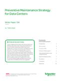
6 External Battery Pack Connector XL models: Use the battery pack connector to connect optional external battery pack(s). These units support up to ten external battery packs. See the APC web site, for the correct external battery pack model number for your UPS. TVSS Screw The UPS features a transient voltage surge-suppression (TVSS) screw for connecting the ground lead on surge suppression devices such as tele-phone and network line protectors. When connecting grounding cable, disconnect the unit from the utility power outlet. 4 2: OPERATION SMART-UPS FRONT PANEL Power On Power Off Load Battery Charge Online The online LED illuminates when the UPS is supplying utility power to the con-nected equipment.
7 If the LED is not lit, the UPS is either not turned ON, or is sup-plying battery power. AVR Trim This LED illuminates to indicate the UPS is compensating for a high utility voltage. 5 AVR Boost This LED illuminates to indicate the UPS is compensating for a low utility voltage. On Battery When the on battery power LED is lit the UPS is supplying battery power to the connected equipment. When on battery, the UPS sounds an alarm four beeps every 30 seconds. Overload The LED illuminates and the UPS emits a sustained alarm tone when an overload condition occurs. Replace Battery Failure of a battery self-test causes the UPS to emit short beeps for one minute and the replace battery LED illuminates. Refer to Trou-bleshooting in this manual.
8 Battery Disconnected The replace battery LED flashes and short beep is emitted every two seconds to indicate the battery is disconnected. Automatic Self-Test The UPS performs a self-test automatically when turned on, and every two weeks thereafter (by default). During the self-test, the UPS briefly operates the connected equip-ment on battery. If the UPS fails the self-test, the replace battery LED lights and immediately returns to online operation. The connected equipment is not affected by a failed test. Recharge the battery for 24 hours and perform another self-test. If it fails, the battery must be replaced. Manual Self-Test Press and hold the button for a few seconds to initiate the self-test. On Battery Operation The Smart-UPS switches to battery operation automatically if the utility power fails.
9 While running on battery, an alarm beeps four times every 30 seconds. Press the button (front panel) to silence the UPS alarm (for the current alarm only. If the utility power does not return, the UPS continues to supply power to the connected equipment until the bat-tery is exhausted. If PowerChute is not being used you must manually save your files and power down before the UPS turns off. DETERMINING ON BATTERY RUN TIME UPS battery life differs based on usage and environment. It is recommended that the battery/batteries be changed once every three years. See the APC web site, , for on battery run times. 6 3: USER CONFIGURABLE ITEMS NOTE: SETTINGS ARE MADE THROUGH SUPPLIED POWERCHUTE SOFTWARE OR OPTIONAL SMART SLOT ACCESSORY CARDS. FUNCTION FACTORY DEFAULT USER SELECTABLE CHOICES DESCRIPTION Automatic Self-Test Every 14 days (336 hours) Every 7 days (168 hours), On Startup Only, No Self-Test This function sets the inter-val at which the UPS will execute a self-test.)
10 Refer to your software manual for details. UPS ID UPS_IDEN Up to eight characters to define the UPS Use this field to uniquely identify the UPS, (ie. server name or location) for net-work management purposes. Date of Last Battery Re-placement Manufacture Date Date of Battery Replacement mm/dd/yy Reset this date when you replace the battery module. Minimum Capacity Be-fore Return from Shut-down 0 percent 15, 30, 45, 50, 60, 75, 90 percent The UPS will charge its batteries to the specified percentage before return from a shutdown. Voltage Sensitivity The UPS detects and reacts to line voltage distortions by transferring to battery operation to protect the connected equipment. Where power quality is poor, the UPS may frequently transfer to battery operation.