Transcription of A Bi-Directional DC-DC Converter with Minimum Energy ...
1 A Bi-Directional DC-DC Converter with Minimum Energy Storage Elements Leon M. Tolbert1,3, William A. Peterson2, Cliff P. White3, Timothy J. Theiss3, Matthew B. Scudiere3 1 The University of Tennessee 2E&M Power 3 Oak Ridge National Laboratory Electrical and Computer Engineering 6 Emma Street National Transportation Research Center Knoxville, TN 37996-2100 Binghamton, NY 13905 2360 Cherahala Blvd. Tel: (865) 974-2881 Tel: (607) 766-9625 Knoxville, TN 37922 FAX: (865) 974-5483 Fax: (607) 766-9622 Tel: (865) 946-1328 e-mail: Fax: (865) 946-1262 Abstract A proof-of-concept military advanced mobile generator set has been developed. The military generator set uses an internal combustion diesel engine to drive a radial-gap permanent magnet alternator at variable speed.
2 The speed of the engine is determined from a user selectable interface that for a given load and ambient thermal conditions controls the engine to run at its most efficient operating point. The variable frequency, variable voltage produced by the permanent magnet alternator is diode-rectified to a high voltage (~400 V) dc link, and an inverter is used to produce selectable frequency, controllable ac voltage. As part of the power electronics for this unit, a 7 kW Bi-Directional DC-DC Converter has also been developed. The Converter can charge 24V batteries that are used to start the internal combustion engine and to power auxiliary low voltage dc loads. Additionally, the Bi-Directional Converter can also draw power from the batteries to help maintain the high voltage dc link during severe load transients.
3 Because of stringent weight and volume requirements for this application, the Minimum in Energy storage elements (high frequency transformers, capacitors, and inductors) was used. This paper presents a description and experimental analysis of this novel DC-DC Converter design. I. INTRODUCTION The Department of Defense has initiated a program to upgrade and develop enhanced tactical power systems to provide reliable electrical power in the battlefield. One aspect of this program is for the development of advanced mobile generator sets in the medium power (5-60kW) range. These future generator sets are to be portable, lightweight systems that are electronically controlled, signature suppressed, and capable of operating on DF-2/JP-8 fuels in extreme environmental conditions.
4 Existing military gen-sets in the medium power range have been designed to be extremely rugged, cost-effective sources of power. These units are significantly heavier than their industrial counterparts to meet the stringent ruggedness requirements of the military and because the units provide additional features and capabilities that are not available on industrial units. Military mobile electric generators are designed to operate in a temperature range from -45 C to 60 C and at altitudes ranging from sea level to 3000m. Existing military gen-sets have a diesel combustion engine that is governed to run at a fixed speed such that the directly coupled alternator driven by the engine produces a fixed frequency output of either 50 or 60 Hz in some units or 400 Hz in other units.
5 Brushless synchronous machines are presently used to convert the mechanical power of the rotating shaft into three-phase electrical voltage at a preset frequency. In order to reduce their logistics burdens, the DOD would like future gen-sets to be much lighter, smaller in volume, more fuel-efficient, quieter, and more reliable than the existing units. Fixed-speed engines are forced to run outside their optimum fuel consumption envelope when these units are not run near full load; therefore, running the engine at variable speed and using power electronics to convert the variable voltage and frequency to a fixed voltage and frequency can allow more efficient operation of the gen-set [1-7].
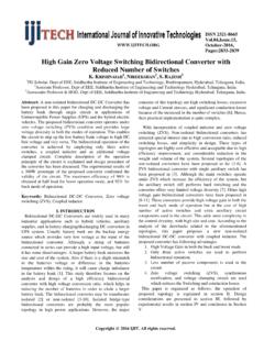
6 With advanced diesel engines and variable speed technology, goals for the program were to reduce weight by almost 50% and increase efficiency by up to 30. II. SYSTEM DESCRIPTION A block diagram of the electronic power conversion system for the proof of concept generator set developed at the Oak Ridge National Laboratory (ORNL) is shown in Fig. 1 [1]. The military generator set uses an internal combustion diesel engine to drive a radial-gap permanent magnet alternator at variable speed. The speed of the engine is determined from a user selectable interface that for a given load and ambient thermal conditions allows the engine to run at its most efficient operating point.
7 The variable frequency, variable voltage produced by the permanent magnet alternator is diode-rectified to dc voltage, and an inverter is used to produce selectable frequency, controllable ac voltage. The user is allowed to select single-phase 120 V, dual-phase 120/240 V, or three-phase 120/208 V. Each of these voltage configurations can be generated at 50 Hz, 60 Hz, and 400 Hz such that the unit can be compatible with equipment produced from around the world or for aerospace applications. The power conversion system also incorporates a Bi-Directional DC-DC Converter that can charge 24V batteries that are used to start the IC engine and to power auxiliary loads, or 0-7803-7420-7/02/$ (C) 2002 IEEE the Converter can draw power from the batteries to help maintain the dc link during severe load transients.
8 The gen-set was designed such that the inverter can produce 120 Vrms line-neutral voltage for dc link voltages between 350 Vdc and 450 Vdc. During normal operation, the alternator line-line voltage is rectified by the three-phase, full-bridge rectifier with conventional six-pulse rectification. The Minimum desired dc link voltage of 350 Vdc corresponds to an alternator speed of 2800 rpm. When the DC link voltage produced by this normal mode of rectification is less than 350 Vdc (corresponding to a gen-set speed of 2000 to 2800 rpm), an asynchronous boost circuit becomes active to maintain the dc link voltage. The circuit that boosts the alternator voltage when the speed is low operates asynchronously with rotor position.
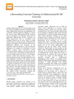
9 However, for a large transient load (such as starting an induction motor), another means is needed to boost the dc link voltage. During these transient times, the Bi-Directional DC-DC Converter could supply power from a battery set to keep the dc link voltage above 350 V. The Bi-Directional circuit operation is described in section IV. III. ASYNCHRONOUS BOOST OPERATION The gen-set was designed such that the inverter can produce 120 Vrms line-neutral voltage for dc link voltages between 350 Vdc and 450 Vdc. During normal, unboosted operation, the alternator line-line voltage is rectified by the three-phase, full bridge rectifier D1 in conventional six-pulse rectification as shown in Fig.
10 2. During this mode, the boost rectifier is inactive and transistor Q1 is off. The Minimum desired dc link voltage of 350 Vdc corresponded to an alternator speed of 2800 rpm. When the DC link voltage produced by this normal mode of rectification is less than 350 Vdc (corresponding to a gen-set speed of 2000 to 2800 rpm), the asynchronous boost circuit becomes active to maintain the dc link voltage. The circuit that boosts the alternator voltage when the speed is low operates asynchronously with rotor position. When the boost is active, transistor Q1 turns on and effectively shorts out the alternator through the full-bridge rectifier D2 shown in Fig. 2. During this time, the three-phase full-bridge rectifier diodes in D1 block, and capacitor C1 supplies the inverter load.