Transcription of A BRIEF INTRODUCTION TO CENTRIFUGAL PUMPS
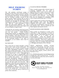
1 A BRIEF INTRODUCTION TO figure below is a cross section of a CENTRIFUGAL pump and shows the two basic parts. CENTRIFUGAL PUMPS . Joe Evans, IMPELLER. This publication is based upon an introductory, half day class that I presented many years ago. It is designed to provide the new comer with an entry level knowledge of CENTRIFUGAL pump theory and operation. Of equal importance, it will make him aware of those areas that will require additional study if he is to become truly VOLUTE. proficient. You will notice references to our Puzzler . Figure 1. These brain teasing discussions investigate the specifics of PUMPS , motors, and their The CENTRIFUGAL pump's function is as simple controls and can be downloaded from the as its design.
2 It is filled with liquid and the education section of our web site. This impeller is rotated. Rotation imparts energy INTRODUCTION , on the other hand, is much to the liquid causing it to exit the impeller's more structured and sticks to the basics. vanes at a greater velocity than it possessed when it entered. This outward flow reduces Some of the figures you will see have been the pressure at the impeller eye, allowing reduced in size substantially. If you have more liquid to enter. The liquid that exits the difficulty reading them, just increase their size impeller is collected in the casing (volute). using the Acrobat scaler. If you have where its velocity is converted to pressure comments or suggestions for improving our before it leaves the pump's discharge.
3 Educational material, please email me at A Very BRIEF History The CENTRIFUGAL pump was developed in INTRODUCTION Europe in the late 1600's and was seen in the United States in the early 1800's. Its wide spread use, however, has occurred only in the Definition & Description last seventy-five years. Prior to that time, the vast majority of pumping applications By definition, a CENTRIFUGAL pump is a involved positive displacement PUMPS . machine. More specifically, it is a machine that imparts energy to a fluid. This energy The increased popularity of CENTRIFUGAL PUMPS infusion can cause a liquid to flow, rise to a is due largely to the comparatively recent higher level, or both. development of high speed electric motors, steam turbines, and internal combustion The CENTRIFUGAL pump is an extremely simple engines.
4 The CENTRIFUGAL pump is a relatively machine. It is a member of a family known high speed machine and the development of as rotary machines and consists of two basic high speed drivers has made possible the parts: 1) the rotary element or impeller and 2) development of compact, efficient PUMPS . the stationary element or casing (volute). The Since the 1940's, the CENTRIFUGAL pump has to the circle) and the volume that flows out become the pump of choice for many (per unit time) depends upon the velocity ( in applications. Research and development has ft/sec) of the rotating pail. The faster the pail resulted in both improved performance and rotates the greater the CENTRIFUGAL force and new materials of construction that have therefore the greater the volume of water greatly expanded it's field of applicability.
5 It discharged and the distance it carries. is not uncommon today to find efficiencies of 93%+ for large PUMPS and better than 50% The description above could be considered for small fractional horsepower units. that of a crude CENTRIFUGAL pump (sans volute of course). It demonstrates that the flow and Modern CENTRIFUGAL PUMPS have been built to head (pressure) developed by a CENTRIFUGAL meet conditions far beyond what was pump depends upon the rotational speed and, thought possible fifty to sixty years ago. more precisely, the peripheral velocity of its PUMPS capable of delivering over 1,000,000 impeller (pail). gallons per minute at heads of more than 300. feet are common in the nuclear power industry.
6 And, boiler feed PUMPS have been Peripheral Velocity & Head developed that deliver 300 gallons per minute at more than 1800 feet of head. Gravity is one of the more important forces that a CENTRIFUGAL pump must overcome. You will find that the relationship between final THEORY velocity, due to gravity, and initial velocity, due to impeller speed, is a very useful one . In operation, a CENTRIFUGAL pump slings . liquid out of the impeller via CENTRIFUGAL force. If a stone is dropped from the top of a Now CENTRIFUGAL force, itself, is a topic of building it's velocity will increase at a rate of debate. Although I will not go into detail feet per second for each second that it here, it is considered by many, including falls.
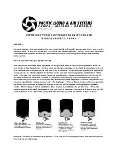
7 This increase in velocity is known as myself, to be a false force. For our purposes acceleration due to gravity. Therefore if we here, we will assume that it is a real force. ignore the effect of air resistance on the falling Refer to the False Force Puzzler for more stone, we can predict the velocity at which it information. will strike the ground based upon its initial height and the effect of acceleration due to CENTRIFUGAL Force gravity. A classic example of the action of CENTRIFUGAL The equation that describes the relationship of force is shown below. Here, we see a pail of velocity, height, and gravity as it applies to a water swinging in a circle. The swinging pail falling body is: v2 = 2gh Where: v = The velocity of the body in ft/sec g = The acceleration due to gravity @ Figure 2 ft/sec/sec (or ft/sec2).
8 Generates a CENTRIFUGAL force that holds the h = The distance through which the body falls water in the pail. Now, if a hole is bored in the bottom of the pail, water will be thrown out. The distance the stream carries (tangent For example if a stone is dropped from a velocity. This relationship is one of the building 100 feet high: fundamental laws of CENTRIFUGAL PUMPS and we will review it in detail a little later. As a v2 = 2 x ft/sec2 x 100 ft finale to this section, let's apply what we have learned to a practical application. v2 = 6440 ft2/sec2 Problem: For an 1800 RPM pump, find the impeller diameter necessary to develop a v = ft/sec head of 200 feet. The stone, therefore, will strike the ground at First we must find the initial velocity required a velocity of feet per second.)
9 To develop a head of 100 feet: This same equation allows us to determine the initial velocity required to throw the stone v2 = 2 gh v2 = 2 x ft/sec2 x 200 ft to a height of 100 feet. This is the case because the final velocity of a falling body V2 = 12880 ft2/sec2. happens to be equal to the initial velocity required to launch it to height from which it v = 113 ft/sec fell. In the example above, the initial velocity required to throw the stone to a height of 100 We also need to know the number of feet is feet per second, the same as its rotations the impeller undergoes each second: final velocity. 1800 RPM / 60 sec = 30 RPS. The same equation applies when pumping water with a CENTRIFUGAL pump.
10 The velocity Now we can compute the number of feet a of the water as it leaves the impeller point on the impellers rim travels in a single determines the head developed. In other rotation: words the water is thrown to a certain height. To reach this height it must start with 113 ft/sec / 30 rotations/sec = ft/rotation the same velocity it would attain if it fell from that height. Since feet traveled per rotation is the same as the circumference of the impeller we can If we rearrange the falling body equation we compute the diameter as follows: get: Diameter = Circumference / . h = v2/2g Diameter = Ft / Now we can determine the height to which a body (or water) will rise given a particular Diameter = Ft or In initial velocity.