Transcription of A Comparison of Radial and Axial View Plasma - …
1 A Comparison of Radial and Axial view PlasmaGeoff TylerJobin Yvon , Horiba GroupLongjumeau, FranceKeywords : Plasma , Radial , Axial , detection limit1 IntroductionThe first paper describing Axial ICP was pub-lished in the mid 1970's (1). However, manyyears passed before the first commercial ICPemerged in 1993, followed by another ICP abouta year later. The latter became an instant suc-cess. The race had started for lower detectionlimits with claims of 10 times better detectionlimits for most elements using an Axial ICP. Butas the atomic spectroscopy community wouldfind out, an Axial Plasma alone was not the sin-gular solution for every Improvement in performanceIt was soon discovered that Axial Plasma sufferedfrom serious interferences caused mainly by ion-ization (2 - 3).
2 Work on the special requirementsof Axial ICP was made to improve the perform-ance. A primary need was to eliminate the fireballregion of the Plasma , while viewing just the cen-tral channel. Improved optical baffling was effec-tive and produced the desired results for axialICP. Improved optical baffling and better resolu-tion improved performance with respect to noisefor the Radial ICPs as well, but for most spec-trometers, this severely restricted the signal, sogains in detection limit were only signal due to the optics has not ledto the improvement in Radial ICPs, except withthe highest resolution ICP spectrometers withlarge optical components. Recent work on high resolution, high optical effi-ciency ICP spectrometers have yielded improveddetection limits with Radial ICP of more than 10times compared with low resolution ICP.
3 The results have led to detection limits on Radial ICPbetter than published detection limits on axialICP (4). The Radial ICP system presented here isthe JY ULTIMA 2 featuring a gigantic 110 x 110mm grating, associated mirrors and a one-meterfocal length monochromator. Light throughput is a key parameter in theamount of signal and, hence, the detection master holographic gratings improvelight throughput compared with ruled and repli-cate holographic gratings, these master holo-graphic gratings also have reduced the amount ofstray light. Stray light raises the background andthus increases noise and background equivalentconcentration (BEC), which in turn has a directeffect on the detection limit. This is one of thelimiting factors with solid state detector (SSD)spectrometers due to the need to use an Echelleoptical system that has high stray light due inpart to the use of very high orders (5).
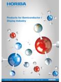
4 Figure 1: Various regions of the plasmaRed= Initial Radiation Zone (IRZ)Blue=Normal Analytical zone (NAZ)Dark red= Molecular region of plasmaICP OPTICAL EMISSION SPECTROSCOPYTECHNICAL NOTE 062 ICP OPTICAL EMISSION SPECTROSCOPYTECHNICAL NOTE 06 Optical coatings have also improved the optical effi-ciency, especially in the low UV tube (PMT) designs have had someimprovements mainly with respect to specializedrequirements, solar blind PMT. The advantageof these particular PMTs is that they are blind aboveapproximately 300 nm. This will minimize multipleorder interferences if more than the first order is uti-lized. Some sequential ICPs use 2nd order light, orin some cases 3rd and 4th orders. The permuta-tions of multiple order use may provide P at in steels if orders beyond the 2ndare Axial viewed ICPA xial ICPs can have improvement factors varyingfrom 10 times down to 2-3 times compared withradial ICP, depending on the resolution of the spec-trometer.
5 The improvements in detection limit, maybe useful for simple environmental applications,albeit for a modest increase in cost. However, radi-al ICPs have been shown to be more robust thanaxial ICPs. The Mg ion/atomic line test promoted byMermet et al (6) is a good test of the "robustness"of the Plasma system to various solutions that maypresent various interferences in the Plasma . This isespecially important where the solutions containcomplex matrices as found in chemicals, metals,and geological samples. The size of the Normal Analytical Zone (NAZ)viewed can affect the accuracy and, of course,recoveries obtained in any tests. Some spectrome-ters view a small region of the Plasma , so that theviewing height becomes an important parameter tooptimize. The NAZ (see figure 1) is above the bulletregion or IRZ (Initial Radiation Zone).
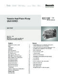
6 It is easy toavoid this region in Radial ICP. However in Axial ICPsit is viewed as well as increasing the path length ofthe NAZ. It is imperative in Axial ICP to avoid thefireball region that surrounds the bullet and presents the engineers with the need to opti-cally baffle the Axial ICP more stringently, resultingin loss of light, to avoid excessive more complex is the matrix, the larger is theproblem. In organic analysis however, the organicbullet cannot be avoided, the whole length of theorganic bullet is viewed. This is why many elementsmay be worse on Axial ICP compared with radialICP, even on a comparable spectrometer, for organ-ic solutions. Figure 2: Cross section of the Plasma and viewingregions of Radial and Axial Axial ICPs the outer tube of the torch has to belonger to contain the Plasma , this presents prob-lems (as with ICP-MS) with dissolved solids.
7 Thesalts attack the outer tube and can increase theconsumable costs dramatically in some cases. Forsome samples the Axial torch may only last Axial ICP there is another parameter to be con-sidered. The Plasma region above the NAZ containselement oxides as the Plasma loses temperatureand combines with the air. Manufacturers often usea shear gas to create a curtain of gas, usually com-pressed air, to cut off viewing this region. Sheargas for elements below 190 nm requires nitrogen,an added cost. An alternative is to have a conewithin the Plasma similar to ICP-MS. The Plasma isviewed without any contribution due to oxides andthus has better background and less interferences,plus the advantage of being able to determine ele-ments in the low UV. However, there is an increasein argon consumption typically an extra view gives more signal intensity due to theincreased observation path length of the NAZ.
8 3 ICP OPTICAL EMISSION SPECTROSCOPYTECHNICAL NOTE 06 This leads to an improved detection limit by 2-3times for high resolution increases in the Axial viewwhile background stays the same, so overall SBRincreases and detection limits limited aperture is required to view the NormalAnalytical Zone (NAZ) channel, without includingthe fireball region of the Plasma , however while theplasma tail can be eliminated by shear gas or a conewith an Argon counter flow gas, the bullet regionobservation cannot be avoided. 4 Radial ICPLess matrix effects are found in Radial ICP comparedto Axial viewing, due to the fact that the IRZ (or bul-let region) is not viewed and can be avoided bychoice of the viewing height. Less spectral interfer-ences are found in Radial viewing, especially organ-ics, due to the reduction of band structuresobserved.
9 No torch adjustment is required for eachelement if you view the entire Normal AnalyticalZone (NAZ) and as the RF power and Plasma gasare generally lower, any sample matrix can be runon Radial ICP. Another advantage of the Radial ICP isthat due to the optical "thinness" of the Radial plas-ma compared with the Axial Plasma , there is awider linear dynamic maintenance and less attention is required tothe smaller Radial torch than Axial torch. The axialtorch lifetime is severely degraded by dissolvedsalts and this can reduce torch lifetime, so radialtorches last longer, especially with dissolved salts,reducing the running costs. Lower running costs arefound with Radial viewing, especially when argonconsumption is taken into account, this is becausethere is a counter flow or shear gas required foraxial viewing to eliminate the Plasma tail.
10 This iswhere all the recombination and oxides are found inthe Plasma and should be avoided at all Drawbacks of Axial ICPA xial view has more matrix interferences. In cleanmatrices the signal increases in the Axial view whilethe background stays similar, so the overall SBRincreases and detection limits improve. However, in"difficult" matrices, the signal increase can bematched by an increase in the background, so theSBR can be the same or even worse, resulting inpoor detection limits, especially for low UV Pb,Zn, As, Cd, P, Se and S. Because of the possibilityof viewing the fireball region of the Plasma , the slitsand much optical baffling is required to reduce thehigh stray light. However, some systems have lowefficiency optical systems, so the alignment ofthese Axial systems is critical for both detectionlimit and interferences ICP cannot eliminate viewing the bullet regionof the Plasma , this leads to high band structuresbeing observed.