Transcription of A Design Example for a Rectangular Concrete Tank PCA ...
1 A Design Example for a Rectangular Concrete Tank PCA Design Method CVEN 4830/4434 University of Colorado, Boulder Spring Semester 2008 Prepared by Ben Blackard The Portland Cement Association (PCA) has publications for designing Rectangular and circular tanks. Some of the Design provisions differ from that of the American Concrete Institute (ACI) specifications. Many in the industry use these PCA Design concepts, so we will adapt them for our calculations as well. Much of the PCA publication is comprised of tables of coefficients for calculating moment and shear in two-way slabs.
2 These tables should simplify the calculations. We will refer to the PCA Rectangular Concrete Tanks Design manual as PCA-R, and the circular tank Design manual as PCA-C. An additional safety factor is used for the loads called the Sanitation Coefficient , we will denote it with SC for brevity. Note that this notation is not an industry standard. The purpose of the sanitation coefficient is to indirectly reduce the stress, and thus the strain, in the steel reinforcing. The result is lower strain in the Concrete , and thus less cracking.
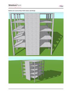
3 The ultimate load will be multiplied by SC, which has different values for different calculations: for flexure SC= for direct tension (hoop tensile stress in reinforcing) shear provided by Concrete for shear beyond that provided by Concrete Another change is the fluid load factor is rather than as stated in the ACI specification. For the purposes of this class, the following load combinations and factors will be used: Mu = ( + + ) for flexure Pu = ( + + ) for direct tension (hoop tensile stress in reinforcing) Pu = ( + + ) for direct compression (hoop compression stress in Concrete ) Vu = ( + + ) shear provided by Concrete Vu = ( + + ) for shear beyond that provided by Concrete D = dead load F = fluid pressure H = earth pressure Rectangular Concrete Tank Design Example An open top Concrete tank is to have three chambers, each measuring 20 60 as shown.
4 The wall height is 17 . The tank will be partially underground, the grade level is 10 below the top of the tank. The highest groundwater table is expected to be 4 below grade. The fluid level inside the tank is 15 . 20 20 60 20 f c = 3,500 psi fy = 60,000 psi soil bearing capacity = 2,700 psf walls above the groundwater table should be designed using a lateral earth pressure equivalent to that developed by a fluid weighing 45 pcf, below the groundwater table use 95 pcf. Due to the settlement characteristics of the soil, it is recommended that the bearing pressure be kept as constant as possible for the full tank loading scenario.
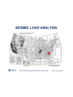
5 Assume the density of the fluid in the tank is 63 pcf. Interior Wall Design Boundary condition case 3 in chapter 2 of PCA-R will be used for determining the applied moments to the tank walls (pages 2-17 thru 2-22). Consider the 15 water depth to be the height of the wall. fixed free fixed fixed qb a a = 15 b = 60 b/a = q = (15 )(63 pcf) = 945 psf From page 2-18 of PCA-R, the maximum vertical moment coefficient is 149, looking at the Mx table. This moment occurs at the center-bottom of the wall. Similarly, the My table gives a maximum horizontal moment coefficient of 99, located at the top ends of the wall.
6 For the moment calculations qu = ( )( )(945 pcf) = 2,089 psf Mu = moment coefficient qu a2/1000 Vertical Moment: coef = 149 Mu = 70,034 lb-ft/ft Horizontal Moment: coef = 99 Mu = 46,533 lb-ft/ft The maximum shear in the wall is obtained from the maximum shear coefficient from page 2-17 of PCA-R, in this case Cs = The wall will be designed for the Concrete to resist the entire shear force. For the shear calculation qu = ( )( )(945 pcf) = 1,607 psf Vu = Cs qu a = ( )(1,607 psf)(15 ) = 12,053 lb/ft Note: The moment in the wall varies considerably for different locations in the wall.
7 The reinforcing could differ at several locations for a highly efficient Design . The thickness of the wall could also vary, either tapering the wall or stepping the wall. However, for the sake of time, the reinforcing will be kept consistent for the entire wall. One Design for the vertical moments, and the other for the horizontal moments. This is a common practice in engineering. Time is not only saved for the Design engineer, but also the detailers and construction crew saves time as compared to a more complicated Design .
8 This Design philosophy is entitled to change if substantial material savings could be realized and if time permits. Vertical Flexure Design of Interior Wall: try a 14 thick wall with 2 clear Concrete cover and #8 bars @ 6 ( Design a 1 wide vertical strip of wall) bw = 12 d = 14 - 2 - bar dia/2 = Ag = 168 in2 f c = 3,500 psi fy = 60,000 psi As = in2 () fAc = = in Mn =() 2c = 867,898 lb-in/ft = 72,325 lb-ft/ft Mu = 70,034 lb-ft/ft Mn = 72,325 lb-ft/ft minimum flexural steel ACI 350-06 sywAfdb200 = in2 [flexure steel As = in2] ACI 350-06 swycAdbff3 = in2 [flexure steel As = in2] minimum vertical wall steel ACI 350-06 Ag As = in2 [total steel As = in2] minimum steel for temperature and shrinkage ACI 350-06 Ag As = in2 [total steel As = in2] maximum flexural steel ACI 318 ()
9 Ysycw1maxs, + == in2 [flexure steel As = in2] Horizontal Flexure Design of Interior Wall: The wall is 14 thick, place the horizontal bars inside of the vertical bars. Try #8 bars @ 8 bw = 12 d = 14 - 2 - vertical bar dia - bar dia/2 = Ag = 168 in2 f c = 3,500 psi fy = 60,000 psi As = in2 () fAc = = in Mn =() 2c = 608,174 lb-in/ft = 50,681 lb-ft/ft Mu = 46,533 lb-ft/ft Mn = 50,681 lb-ft/ft minimum flexural steel ACI 350-06 sywAfdb200 = in2 [flexure steel As = in2] ACI 350-06 swycAdbff3 = in2 [flexure steel As = in2] minimum vertical wall steel ACI 350-06 Ag As = in2 [total steel As = in2] minimum steel for temperature and shrinkage ACI 350-06 Ag As = in2 [total steel As = in2] maximum flexural steel ACI 318 ()
10 Ysycw1maxs, + == in2 [flexure steel As = in2] Shear Capacity (1 wide strip either way): bw = 12 d = f c = 3,500 psi lb/ft16,328dbf2 Vwcc= = Design shear strength = Vn = = 12,246 lb/ft Vu = 12,053 lb/ft Vn = 12,246 lb/ft Long Exterior Wall The Long exterior wall has the same geometry as the interior wall. A simple demonstration shows that the effect of the interior fluid is significantly greater than the exterior soil and groundwater. The long exterior wall will take the same Design as the interior walls .