Transcription of A Dual-Band Walking Stick
1 A Pedestrian-Portable 2m/70cm Walking Stick Antenna for the Ham Gentleman Walk about freely with this pedestrian-portable antenna. Use it for better coverage at a parade, a bike-a-thon or just on a stroll. Alternately, hang it in a tree or mount it permanently. Its utility will impress you. It is also an ideal low-cost ham radio club project. By John Portune W6 NBC and Ernie Sloan W6ND Over the centuries Walking sticks have held surprises stilettos, whiskey flasks, fencing foils, even guns. James Bond, eat your heart out. This version conceals an efficient highly-portable Dual-Band VHF/UHF antenna that will greatly extend the range of your HT.
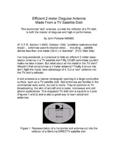
2 2m/70cm portables are often seen clamped to a picnic table, mounted on a tripod, or hung from a tree. But recently at a parade it struck me that a more versatile design might be a classical gentleman s Walking - Stick antenna. Figure 1. It s very portable. Hold it up when you want good range. Or use it as a Walking Stick to change locations. And, of course, you can still hang it up in a tree. Figure 1: W6 NBC holding gentleman ham s Walking Stick Thinking about how to make one, my first question was the type of antenna to use in the Stick ?
3 My first thought was a J-pole, perhaps made from 300 Ohm twin lead a popular DIY design? But too long 38 in. (antenna) + 19 in. (matching stub). So what about a coaxial dipole? It s much shorter and just as good a performer? (See side bar). Choke Coaxial Dipole But rather than a conventional coaxial dipole (side bar right), this coaxial takes advantage of two innovations: (1) no coaxial sleeve, and (2) 70cm stubs for a better radiation pattern on the 440 MHz band . (Side Bar) For readers unfamiliar with the coaxial dipole, the classical design consists of a monopole spike mounted over a cylindrical metal sleeve, closed at the top, open at the bottom.
4 (right). Coaxial Dipoles: Conventional (right), Choke (left) The feed coax enters through the bottom end of sleeve and runs up to the center of the antenna. There the inner conductor connects to the spike and the shield to the sleeve. It s technically a center-fed dipole. What s more, it has the same performance as a J-pole, but is shorter and usually narrower. On the left is the alternate version, a choke coaxial, described in the accompanying article. No Coaxial Sleeve To understand how the sleeve may be omitted, picture this.
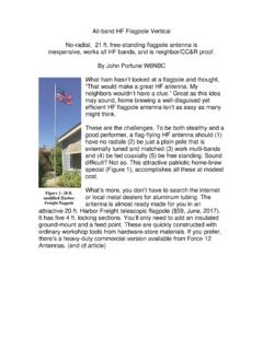
5 When RF arrives at the center feed point, it not only runs upward on the spike but also downward on the outside of the shield. However, the choke, down the coax, blocks the currents going any farther down the shield. This is the same as what happens at the open end of the sleeve of a conventional coaxial dipole. Hence, this part of the coax shield now performs the same function as the sleeve. But this variant is smaller in diameter more suitable for the Walking Stick . The choke is seven turns of the feed coax wrapped around the outside of the Walking Stick , just below the handle.
6 Figures 2 & 8. This number of turns is the minimum necessary to achieve a choke inductance of roughly 1 H needed for 2m. More turns and length would have been needed had the choke been put inside the shaft. Incidentally, both authors tried using VHF-mix ferrite beads in place of the coax choke and were entirely unsuccessful. Comments are welcomed here. Figure 2: Handle of the Walking Stick showing the 7-turn choke and the feedline pigtail. You may mount a connector instead, if you prefer. dual -banding the Antenna The second innovation was to achieve a good radiation pattern on both bands.
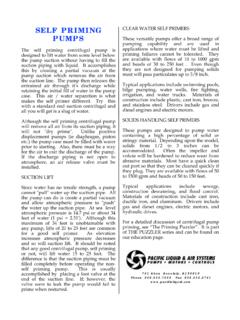
7 Many hams know that a 2m antenna can exhibit a low SWR on 70cm. That s because the 440 MHz band is close to the third harmonic of 2m. But what many hams are not aware of is that the radiation pattern of a plain 2m dipole or J-pole used on 70 cm is poor. Many J-pole home builders ignore this. They assume that a low SWR is all they need to achieve. Not so, notice Figure 3. As you can see, much the energy goes in the wrong direction. Figure 3: 2m dipole or J-pole (free-space) vertical radiation pattern (black) and the same antenna on 70cm (red).
8 Fortunately, there is an easy solution. Install 70cm stubs on the 2m antenna to create a good UHF radiation pattern. Many commercial HF antennas use this technique to achieve good patterns on their multi- band antennas. Here s how the stubs work. Transmission line theory dictates that the open end of a shorted stub looks like an open circuit. If we place two 70cm stubs, one above and the other below the feed point, the outer ends of the antenna will disappear on 70cm and the radiation pattern will be ideal. Note the improvement in Figure 4.
9 Figure 4: Vertical (free-space) radiation patterns on 2m (black), and 70cm (red) stubs installed Without the stubs the antenna is 1 on 70cm, yielding the poor radiation pattern of Figure 3. But with the stubs installed the antenna becomes a dipole as it also is on 2m. The stubs merely add end loading on 2m, shortening the overall antenna by roughly 3 to 5 in, but have no effect on the 2m Figure 5 shows the SWR curves for the antenna on both bands. Because 2m and 70cm are not in an exact 3 to 1 frequency ratio, some of the dimensions shown had to be slightly compromised.
10 Note that the resulting SWR dip is just a little high in frequency on 2m and low on 70cm. This is not a problem, however. Theory predicts that the losses are very small on any antenna when the SWR is under 2 to 1. It is even quite acceptable under 3 to 1. Figure 5: SWR curves. Note the small compromise of center frequencies. Mechanical Issues To keep with tradition, the outside of the Walking Stick is made from every ham s favorite DIY material common PVC pipe ( in.). What would hams do without PVC pipe? If you are also a woodworker you might consider using a real cane to hold the antenna.