Transcription of A GUIDE FOR ULTRASONIC TESTING AND ... - Ship Structure
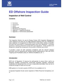
1 SSC-21 3.. h,..:.- .,, ~, .. :.Z.+. A GUIDE FOR ULTRASONIC TESTING AND. EVALUATION OF WELD FLAWS. This document has been approved for public release and sale; its distribution is unlimited. i SHIP Structure COMMITTEE. I 970. SHIP Structure COMMITTEE. MEMBER AGENCIES: ADDRESS CORRESPONDENCE TO: UNITED STATES COAST GUARD SECRETARY. NAVAL SHIP sys TEMs COMMAND SHIP Structure COMMITTEE. MILITARY SEA TRANSPORTATION sERVICE COAST GUARD HEADQUARTERS. MARITIME ADMINISTRATION WASHINGTON, 20591. AMERICAN BUREAU OF SHIPPING. 1970. Dear Sir: 10 maintain the high degree of safety and reli- ability in ship fabrication, the Ship Structure Committee has completed a project that provides an ULTRASONIC inspec- tion quide that retain~ the comparable radiographic standard provided earlier. The results of this project are contained in this report, Rear Admiral, U,S.
2 Coast Guard Chairman, Ship Structure Committee :!i , -, SSC-213. Final Report on Project SR-188,, [ ULTRASONIC Test GUIDE . to the Ship Structure Committee A GUIDE FOR ULTRASONIC TESTING AND EVALUATION. OF MELD FLAWS. by R. A. Youshaw Naval Ordnance Laboratory under Department of the Navy Naval Ship Engineering Center Project No. SF 35422306. Task 02022. This document haz been approved foY public release and sale; its dist~ibution is unlimited. U. S. Coast Guard Headquarters Washington, 1970. ABSTRACT. This document presents procedures and acceptance limits for contact ULTRASONIC inspection of steel butt welds in the thickness range of 1/4 to 2 inches. The acceptance limits de- scribed in the following sections are compatible with those set forth in SSC-177, GUIDE for Interpretation of Nondestructive Tests of Welds in Ship Hull Structures for radiographic inspec- tion and should therefore result in satisfactory ship welds.]
3 Ii SHIP Structure COMMITTEE. The SHIP Structure COMMITTEE is constituted to prosecute a research program to improve the hull structures of ships by an extension of knowledge pertaining to design, materials and methods of fabrication. RADM W. F. Rea, 111, USCG, Chairman Chief, Office of Merchant Marine Safety U. S. Coast Guard Headquarters Capt. Riblett, USN Mr. E. S. Dillon Head, Ship Engineering Division Deputy Chief Naval Ship Engineering Center Office of Ship Construction Maritime Administration Capt. T. J. Banvard, USN. Maintenance and Repair Officer Mr. C. J. L. $choefer, Vice President Military Sealift Command American Bureau of Shipping SHIP Structure SUBCOMMITTEE. The SHIP Structure SUBCOMMITTEE acts for the Ship Structure Committee on technical matters by providing technical coordination for the determination of goals and objectives of the program, and by evaluating and interpreting the results in terms of ship structural design, construction and operation.
4 NAVAL SHIP ENGINEERING CENTER U. S. COAST GUARD. Mr. J. B. O'Brien - Acting Chairman LCDR C. S. Loosmore, USCG - Secretary Mr. J. B. O'Brien - Contract Administrator CDR C. R. Thom~son. USCG - Member Mr. G. Sorkin - Member LCDR J. W. Kime, U~CG - Alternate Mr. H. S. Sayre - Alternate Capt. L. A. Colucciello, USCG - Alternat~. Mr. I. Fioriti - Alternate NATIONAL ACADEMY OF SCIENCES. MARITIME ADMINISTRATION. Mr. A. R. Lytle, Liaison Mr. F. Dashnaw - Member Mr. R. W. Rumke, Liaison Mr. A. Maillar - Member Prof. R. A. Yagle, Liaison Mr. R. Falls - Alternate Mr. W. G. Frederick - Alternate SOCIETYOF NAVAL ARCHITECTS & MARINE. AMERICAN BUREAU OF SHIPPING ENGINEERS. Mr. S. G. Stiansen - Member Nr. T. H. Buermann, Liaison Mr. F. J. Crum - Member OFFICE OF NAVAL RESEARCH AMERICAN IRON AND STEEL INSTITUTE. Mr. J. M. Crowley - Member Dr.
5 W, G. Rauch - Alternate Mr. J. R. LeCron, Liaison NAVAL SHIP RESEARCH & DEVELOPMENT CENTER BRITISH NAVY STAFF. Mr. A. B. Stavovy - Alternate Dr. V. Flint, Liaison CDR P. H. H. Ablett, RCNC, Liaison MILITARY 5 EALIFT COMMAND WELDING RESEARCH COUNCIL. Mr. R. R. Askren - Member Mr. K. H. Koopimn, Liaison Lt. J. G. T. E. I<oster,USN, - Member Mr. C. Larson, Liaison iii CONTENTS. SCOPE..1. TEST METHOD ..1. PERSONNEL QUALIFICATION..3. CALIBRATION STANDARDS..4. INSTRUMENT CALIBRATION ..4. WELD INSPECTION..5. DISCONTINUITY LENGTH DETERMINATIONS..5. DISCONTINUITY EVALUATION ..8. RECORD OF INSPECTION ..8. GLOSSARY OF TERMS.. 11. iv . SCOPE. This document presents procedures and acceptance limits fOr COntact ULTRASONIC inspect~n of steel butt welds in the thickness range of 1/4 to 2 inches. The acceptance limits described in the following sections are compatible with those set forth in SSC-177, GUIDE for Interpretation of Nondestructive Tests of Welds in Ship HU1l Structures for radiographic inspection and should therefore result in satis- factory ship welds.
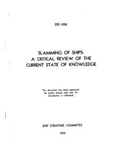
6 Occasions may arise where radiographic inspection could provide additional information. TEST METHOD. General - The procedures given apply to the contact ULTRASONIC inspection of butt welds. Weld inspection is accomplished by introducing shear waves into a Plate at a selected angle and manipulating the transducer so as to scan the entire weld$ Fig. A-l. \,/'-- FIG. A-1. TECHNIQUE FOR INSPEC rIiiGBIJT'i ldELESMITH SHEAR WAVES. EuuiPment - The ULTRASONIC instrument shall be of Ehe pulse-echo type with an A-scan presentation. It shall be capable of generating~ receiving and displaying screen pulses from 1 to 5 MHz on the cathode ray tube. The instrument shall have a circuitry to provide a continuously increasing ampli- fication with respect to time or distance of travel. A. calibrated decibel attenuator control is recommended.
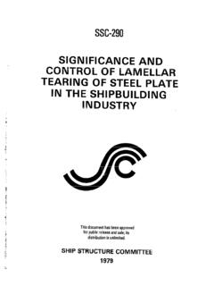
7 Battery -.. -2- powered equipment must contain an alarm to signal battery depletion prior to instrument shut-off due to battery exhaustion. Transducers - The maximum dimension (manufacturers'. specifications) of the transducer active element shall not exceed one inch. A ratio of 2:1 width to height of the active element is recommended. A nominal test frequency of MHz is recommended. Selection of Probes - The primary consideration for selecting a probe shall be the thickness of the plate. The following shear wave angles are recommended: 70 for plate thicknesses 1/4 to 1/2 . 60 or 70 for platie thicknesses 1/2 to 1-1/2' . 45 or 60 for plate thicknesses l-l\2 to 2-112 . The transducer angle should be checked periodically with the International Xnstitute of Welding Test Block, Fig. A-2. Couplant - A liquid such as glycerin diluted with alcohol or water and to which a wetting agent has been added is recommended for acoustic coupling between the transducer and the plate.
8 Most oils are acceptable. For overhead work and for places of difficult access certain types of grease may ,200~r2 .. r 15. A 41 G ,/'400. 509 60 L. I-35+ \. PLASTICDISC. NOTE: ALL DIMENSIONS IN MILLIMETERS. 1 INCH= FIG. A-2. INTERNATIONAL INSTITUTE OF WELDING TEST BLOCK FOR ULTRASONIC CALIBRATION. -3- prove useful. Any couplant should be removed upon completion of the inspection. Surface l?re~aratioq - The average plate as receiv~ from the mill has a surface that is smooth enough for ULTRASONIC inspection. l?latewith loose scale, flaked paint, excess rust, or pitting will require grinding. After welding, the surface of the base metal where the probe is to be manipulated should be cleaned of weld splatter. If surface irregularities on the weld bead interfere with the ULTRASONIC test or cause diffi- culties in interpretation then the weld bead should be ground reasonably smooth.
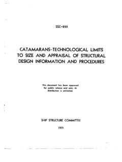
9 Base Metal Inspection - Although the presence of laminations in the base metal may not be a basis for rejection, these reflectors may mask a part of the weld from the ULTRASONIC beam, Fig. A-3, or cause the operator to incorrectly locate a discontinuity Fig. A-4. Laminations can be detected ultrasonically with a straight beam (longitudinal waves) . When laminations are encountered, the inspection should be made from the other side of the weld. Supplement C, ULTRASONIC TESTING Method, TC-lA Recommended PracticeJ American Society for Nondestructive TESTING , shall apply. ULTRASONIC TESTING may be carried out by a Level 11 operator or by a Level I operator under the direct supervision of a Level 11. operator. \ LAMINATION //. x \, /' p ~. \. // \. \ /~ /. FIG. A-3. MASKING EFFECT OF A BASE METAL LAMINATION. P'T-T \.
10 /'. /. ~. \>. ,/ \. \. \. / ACTLJAL. INFERRED. \. DEFFCT ILOCATION. DEtitCT LOCATION. FIG. A-4. POSITIO!I. ERRORSINTRODUCEDBY -4- CALIBRATION STFJJWW13S. A test block shall be prepar- from material experimentally determined to be defect free and which is acoustically similar to thq work material. This block should Ix= 1-1/4 thick with a series of 1/16 diameter drilled holes spaced to provide path lengths equivalent to the longest and shortest path lengths to be used in the weld inspection. intermediate distances should also be provided. The scanning surfaces should be approximately 250 RMS, prepared by the grinding method with the direction of grind parallel to the long dimension of the test block. Figure 5. illustrates an acceptable design. SURFACE FINISH ON THE SCANNING SURFACESTO BE. APPROXIMATELY 250 RMS PREPARED BY GRINDING METIIOD.