Transcription of A Guide to Fiber Bragg Grating Sensors - InTech - Open
1 Chapter 1. A Guide to Fiber Bragg Grating Sensors Marcelo M. Werneck, Regina C. S. B. Allil, Bessie A. Ribeiro and F bio V. B. de Nazar . Additional information is available at the end of the chapter 1. Introduction Optical Fiber Sensors (OFS) appeared just after the invention of the practical optical Fiber by Corning Glass Works in 1970, now Corning Incorporated, that produced the first Fiber with losses below 20 dB/km. At the beginning of this era, optical devices such as laser, photodetectors and the optical fibers were very expensive, afforded only by telecom companies to circumvent the old saturated copper telephone network. With the great diffusion of the optical Fiber technology during the 1980's and on, optoelectronic devices became less expensive, what favored their use in OFS.
2 OFS can be applied in many branches of the industry but we will concentrate here the electrical power industry. In this area, the operators need to measure and monitor some important physical parameters that include: Strain ( ). Vibration of structures and machines Electric current (from A to kA). Voltage (from mV to MV). Impedance ( ). Leakage current of insulators ( A to mA). Temperature Pressure Gas concentration Distance between stationary and rotating or moving parts In the electrical power industry (EPI) we have two facts that can cause collapse of an electronic sensor : presence of high voltage and presence of high electromagnetic interference. Therefore, depending on where we want to measure a parameter it can be very difficult or even impossible to use a conventional sensor .
3 The best option to circumvent this 2013 Allil et al., licensee InTech . This is an open access chapter distributed under the terms of the Creative Commons Attribution License ( ), which permits unrestricted use, distribution, and reproduction in any medium, provided the original work is properly cited. 2 Current Trends in Short- and Long-Period Fiber Gratings is through the use of an OFS, because the Fiber is made of dielectric material sand, therefore, it is possible to place them very close or even over a high potential conductor and they do not necessarily need electrical power at the sensor location. Another problem with conventional Sensors is that they all need electric energy to work. However, providing electric energy at the sensor location is sometimes difficult if the device needs to be far away from any appropriated power supply.
4 It happens in long high voltage transmission lines, at high voltage potentials, along pipe-lines or in deep ocean, for instance. Since OFS are passive Sensors they do not need electric energy to work. Therefore we can mention some, very specific characteristics of OFS that are well exploited when applied to the EPI: High immunity to Electromagnetic Interference (EMI). Electrical insulation Absence of metallic parts Local electrical power not required Lightweight and compactness Easy maintenance Chemically inert even against corrosion Work over long distances Several Sensors can be multiplexed on the same Fiber There are many options to develop an OFS. The easiest way is by making the measurement to modulate the light amplitude that is the power, and ending up with an amplitude modulated sensor .
5 These Sensors were very common at the beginning of OFS era but they gradually were substituted by wavelength based Sensors . These are more stable and self- calibrated as the wavelength does not depend on losses due connectors, modal drifts, macro bends, or LED and LASER ageing/drifts. In this Chapter we will concentrate on a very special type of OFS: the Fiber Bragg Grating (FBG) Sensors . 2. Theory and models of FBG. Fiber Bragg Grating (FBG) technology is one of the most popular choices for optical Fiber Sensors for strain or temperature measurements due to their simple manufacture, as we will see later on, and due to the relatively strong reflected signal. They are formed by a periodic modulations of the index of refraction of the Fiber core along the longitudinal direction and can be produced by various techniques.
6 The term Fiber Bragg Grating was borrowed from the Bragg law and applied to the periodical structures inscribed inside the core of conventional telecom Fiber . Therefore, before entering the theory of Fiber Bragg Grating itself, it is worth to go back one century behind in order to review the Bragg law. Sir William Lawrence Bragg , was born in 1890, a British physicist and X-ray crystallographer, was the discoverer, in 1912, of the Bragg law of X-ray diffraction. This A Guide to Fiber Bragg Grating Sensors 3. principle is used until today for the study and determination of crystal structure, particularly in thin film research. Sir Bragg , together with his father, won the Nobel Prize for Physics in 1915 for an important step in the development of X-ray crystallography.
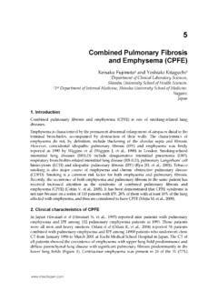
7 Bragg diffraction occurs for an electromagnetic radiation whose wavelength is the same order of magnitude of the atomic spacing, when incident upon a crystalline material. In this case the radiation is scattered in a specular fashion by the atoms of the material and experiences constructive interference in accordance to Bragg 's law. For a crystalline solid with lattice planes separated by a distance d the waves are scattered and interfere constructively if the path length of each wave is equal to an integer multiple of the wavelength. Figure 1 shows the idea. Bragg 's law describes the condition for constructive interference from several crystallographic planes of the crystalline lattice separated by a distance d: 2d sin = n (1).
8 Where is the incident angle, n is an integer and is the wavelength. A diffraction pattern is obtained by measuring the intensity of the scattered radiation as a function of the angle . Whenever the scattered waves satisfy the Bragg condition it is observed a strong intensity in the diffraction pattern, known as Bragg peak. Figure 1. An incident radiation is reflected by the lattice structure of a crystal and will interfere constructively if the Bragg law is obeyed. The first observations of index of refraction changes were noticed in germane silicate fibers and were reported by Kenneth Hill and co-workers in 1978 [1]. They described a permanent Grating written in the core of the Fiber by an argon ion laser line at 488 nm launched into the Fiber by a microscope objective.
9 This particular Grating had a very weak index modulation, resulting in a narrow-band reflection filter at the writing wavelength. In reality, this phenomenon happened by chance, when they injected a high power blue light into de Fiber , unexpectedly, after a few minutes, the transmitted light decayed. It was Friday but they were so puzzled with this phenomenon that Hill returned to his laboratory on Saturday to make a new experiment. He wanted to know where the light was going to and he had a clue. He used a thin microscope slide as a beam splitter in order to monitor a possible 4 Current Trends in Short- and Long-Period Fiber Gratings reflection from the Fiber and there was the missing light [2]. The explanation is that at the end of the Fiber about 4% of the light was reflected by Fresnel reflection which, in its way backwards, interfered with the ongoing light producing an interference pattern.
10 This pattern contained peaks and valleys of a stationary wave which imprinted permanently the pattern into the core of the Fiber as an index of refraction modulation. Initially, the reflected light intensity is low, but after some time, it grows in intensity until almost all the light launched into the Fiber is back-reflected. The growth in back-reflected light was explained in terms of a new effect called photosensitivity . After the inscription of the Grating into de Fiber 's core, due the periodic modulation of the index of refraction, light guided along the core of the Fiber will be weakly reflected by each Grating plane by Fresnel effect. The reflected light from each Grating plane will join together with the other reflections in the backward direction.