Transcription of A Guide to Sizing Orifice Plate Flow Meters - IDC …
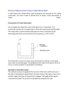
1 A Guide to Sizing Orifice Plate Flow Meters The Orifice Plate is a very robust flow measurement device. It is one device that is very easy to use and can easily be adaptable to many flow measurement applications. Its cost of operation is minimal and familiarity with the device is near universal. All these pluses make the Orifice Plate the first choice measurement device in almost every flow application. It does however have some limitations which makes the Sizing process a little tricky. Two key limitations include: (a) Limited Turn Down (b) Non-linear loss of accuracy at low flow rates as shown by the graph below: As can be observed from the above graph, large errors are introduced into the measurement system by Orifice plates at low flow rates.
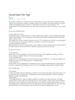
2 This is because flow is proportional to the square root of differential pressure as shown by the graph below: ISO 5167-2:2003, measurement of fluid flow by means of pressure differential devices: Orifice plates This square root relationship between flow and differential pressure for the Orifice plates makes compromise in either flow or differential pressure inevitable in the Sizing process. Mind you, there are other sources of errors in Orifice flow meter measurements. These include variations in pipe diameter, Orifice Plate machining tolerances and errors introduced due to flange taps. The errors introduced by these sources are however minimal. Significant errors can be introduced in the measurement system due to variation in temperature in liquid applications but are usually compensated for in the measurement setup.
3 In gas measurement systems with the Orifice Plate , errors introduced by variation in temperature, static pressure and specific gravity are even more pronounced such that online compensation for these variables have proven to be the best strategy that has yielded the best results. Orifice Plate Sizing Factors: Some Sizing factors greatly impact the accuracy of the Orifice Plate are: (a) Differential Pressure across the Orifice Plate (b) Maximum Flow Rate for the given application (c) Beta Ratio Differential Pressure (DP). The differential pressure(DP) across the Orifice Plate meter is proportional to flow. However the relationship is not linear. At low flow rates, the error in DP measurement becomes large making the device less accurate at low flow.
4 Consequently, a low full-scale DP corresponding to maximum flow introduces errors at low flow rates while a high full-scale DP may achieve good accuracy but may come at a greater energy cost (pumping cost) and a permanent pressure loss in the system which may far outweigh the gain in accuracy. Standard ranges of DP in use are 50 inches, 100 inches and rarely 200 inches of water column. When Sizing , consider using 100 inches instead of 50 inches; 200inches instead of 100 inches but be careful! Maximum Flow The maximum flow is the highest flow that the flow measurement system can handle and still maintain the right accuracy. Selecting an unnecessarily high maximum flow will definitely introduce errors at low flow rates. The right maximum flow should be selected based on actual conditions (arrived at through a flow study of the system that requires the flow measurement ).
5 When done, this will yield the right result in terms of accuracy. Beta RatioAs discussed in flow instrumentation principles the beta ratio ( =. d/D) is the ratio of the Orifice Plate bore diameter (d) and the pipe internal diameter (D). During Sizing , keep your beta ratio in the range to This is the range of beta ratio that gives the best performance from the Orifice Plate . Anything outside this range introduces more errors and other flow problems. Keep in mind that these days, Orifice Plate Sizing is done by software provided in most cases by the Orifice Plate manufacturers themselves. So when Sizing in addition to other factors, ensure you select the right DP. range, maximum flow and an optimum beta ratio for best performance of the Orifice Plate .
6 Note that Beta ratio and DP for the Orifice Plate are related. Altering one alters the other. Source.