Transcription of A Ham's Guide to RFI, Ferrites, Baluns, and Audio ...
1 A Ham's Guide to RFI, ferrites , Baluns, and Audio interfacing Revision 7 Jan 2019. by Jim Brown K9YC. The basis of this tutorial is a combination of my engineering education, 60 years in ham radio, my work as vice-chair of the AES Standards Committee working group on EMC, and extensive re- search on RFI in the pro Audio world where I made my living. That work is documented in techni- cal papers and tutorials that can be downloaded from the publications section of my website. For this latest revision, much of the material on common mode chokes for transmitting has been moved to a new applications note.
2 Chapter 1 Some Fundamentals To solve interference problems, we must understand them. So we'll begin by describing the ways that RF interference is coupled into equipment and detected. There are several principal mecha- nisms at work. You should study this tutorial thoroughly to understand how these things work. Detection at Semiconductor Junctions Every semiconductor junction, whether part of a diode, transistor, or integrated circuit, is quite nonlinear, especially in the voltage region where it is begin- ning to conduct. In analog circuits, we prevent this non-linearity from causing distortion by prop- erly biasing the circuitry, by using lots of negative feedback, and by preventing the signal from be - ing large enough to cross into the cutoff region.
3 Thanks to this non-linearity, every semiconductor junction functions as a square law detector, de- tecting any RF signal it sees. A good designer prevents detection by shielding the equipment and its wiring, by filtering input and output wiring, and even by bypassing the junction by a capacitor. Since virtually all detection that causes RFI follows square law, the strength of the signal detected by Audio equipment, telephones, and other equipment will increase (or decrease) as the square of any increase (or decrease) in RF level at the detector.
4 In other words, the strength of the detected RF changes by twice the number of dB that the RF signal changes. This means that if we manage to reduce the interfering RF signal by 6 dB, the detected Audio will drop by 12 dB. This is a very use - ful thing it means that we may not need "an elephant gun" to solve many interference problems. Antenna Action The most fundamental cause of radio interference to other systems is the fact that the wiring for those systems, both inside and outside the box, are antennas. We may call them "patch cables" or "speaker cables" or "video cables" or "Ethernet cables," or printed circuit traces, but Mother Nature knows that they are antennas!
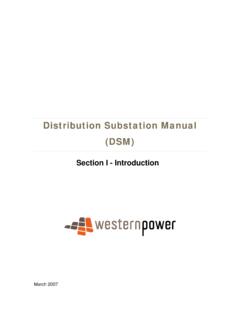
5 And Mother Nature always wins the argument. When we transmit, some of the RF from our transmitter is picked up by those unintentional anten- nas, and RF current flows on them. What happens to that current determines whether there will be interference, and how severe it will be. We know that antennas work in both directions that is, they follow the principle of reciprocity so when RF trash from inside the box flows on those an- tennas, it is radiated as noise and we hear it on the ham bands. Fig 1 shows a simple antenna we've all used, probably with our first radio receiver.
6 We con- nected a random wire to our receiver, and the antenna current flowed through the receiver to a "ground" that might have been a driven rod, but was more likely the safety ground of the AC. power line (the third pin on the AC socket, known in North America as the "green wire"). Even if the radio was double insulated so that it didn't require the green wire connection, RF. current still flowed through the stray capaci- tance of the power transformer to the power line and made the radio work. Fig 1 A simple random wire antenna RF picked up on the antennas we call loudspeaker wiring, video cables, the coax from the cable TV.
7 System or a rooftop TV antenna, flows through equipment to get to the AC power system safety Entire Contents Copyright 2007-19 James W. Brown, except product data, which is copyright by Fair-Rite Products. All Rights Reserved Understanding and Solving RF Interference Problems Page 2. ground. Hams understand that some antennas are more effective than others. An antenna that is close to resonance will work better than one that is not. Long antennas tend to pick up more RF. than short ones. Think about these fundamental principles when trying to diagnose which cables are bringing your RF into a given system (or radiating their trash into your receiving antenna).
8 A path to "ground" or the power system is not always needed to produce antenna action. The whip antenna on our VHF and UHF handheld radios uses the radio, capacity-coupled to our hand that holds it, as a counterpoise (that is, to provide "the other half of the antenna"). All that is required for this to work is that the size of the counterpoise must be a significant fraction of a quarter wave (or larger) so that it can "sink" the antenna current. Common Mode and Differential Mode Signals A differential mode signal is one that exists be- tween the conductors of a cable.
9 At any given point along the cable, current flowing on one con- ductor is precisely balanced by current flowing in the other direction on the other conductor. The intentional signals carried by cables are differential mode signals the Audio or video signal in a home Audio system, Ethernet signals on CAT5/6 cable, and the RF signal carried by the feedline connecting our antennas to our transceivers. A common mode signal is one that places equal voltage on all conductors that is, the voltage be- tween the two ends of the cable are different, but there is no voltage between the conductors.
10 An- tenna action produces a common mode voltage and current along a cable. The antenna current in- duced on Audio and video wiring is a common mode signal. That is, with "ideal" cable, there is no differential voltage between the signal conductors as a result of this antenna action. If the cable is shielded, nearly all of this current flows on the shield (and skin effect causes it to flow on the out- side of the shield). If the shield is ideal (that is, if the current is distributed with perfect uniformity around it), the field inside the shield will be zero, and thus none of this antenna current will flow inside the cable.