Transcription of A high-energy capacitor discharge ignition system …
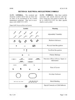
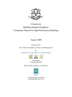
1 A high - energy capacitor discharge ignition system This completely new capacitor discharge ignition system has been designed from the ground up to provide a high energy "multiple spark discharge " to cope with engines which have very high RPM rates. It is intended particularly for use with two stroke engines, high performance four strokes and older vehicles. Twenty or so years ago. capacitor discharge ignition (GDI) was the ac-knowledged "solution for automotive enthusiasts wanting a high energy ignition circuit. GDI gave a really hot spark which would fire virtually any spark plug no matter how fouled or grotty it was. Tens of thousands of enthusiasts installed them on their cars and hence forward swore by them as the greatest innovation system since Karl Benz thought of the horseless 18 SILICON CHIP : these three circuits show the three types of ignition circuit.
2 (a) is the original points-based system . ) shows a typical CDI system which uses a DC-to-DC inverter to charge a capacitor which typically has a value of luF. Each time the switch points in the distributor open, it fires an SCR to dump the capacitors 's charge into the coil primary winding. (c) shows the arrangement of our new CDI system . It has a DC-to-DC inverter with a regulated 300V DC output which charges up a luF capacitor . Instead of using an SCR to dump the capacitor 's charge into the coil, it uses a pair of Mosfets which are depicted as S1, a single pole double throw switch..carriage. Well, maybe it wasn't quite that good but you get the picture. But there was another aspect of CDI which wasn't good and that was "cross-fire". Because the CDI spark was so hot and more importantly, because it had such a fast rise-time of only a few microseconds, it often fired the plugs in other cylinders.
3 This problem was most troublesome in V8s, in some sixes and even some four cylinder cars such as the air-cooled VW which had the spark leads running close and parallel right across the en-gine fan housing. Cross-fire is caused by the capacitance between adjacent spark plug leads. The capacitance between the leads causes the fast-rising voltage from the coil to be coupled into the adjacent leads and thereby can de-liver unwanted sparks in other cylinders. Cross-fire can cause severe engine damage and sounds similar to pinging. Ultimately, CDI fell into disuse for mainstream cars because of the introduction of lean fuel mixtures in an attempt to meet rising anti-pollution standards. The very fast and very short spark of CDI wasn't all that good at igniting lean mixtures.
4 Car manufacturers introduced transistor-assisted ignition with long spark durations to ensure that lean mixtures did bum properly. There was one CDI design which attempted to overcome the lean mixture drawback and that was the so-called "multiple spark discharge " system . However it was a complex design which never really caught on. These days, there is no modern car with an engine management system which uses CDI, to our knowledge. Whether they are single coil, multi-coil or direct-fire systems, they are all variants of the tried and true transistor assisted ignition (TAI) system . So why design a new CDI? At SILICON CHIP, we have tended to disparage CDI systems for years, knowing that our very popular high - energy TAI system has a well-earned reputation for reliability.
5 Gut some readers were not about to be put off. They wanted a CDI design and they wanted it for a number of reasons. They wanted them for two-stroke and four-stroke motors on motor bikes, out- boards and Go-Karts. And they wanted them for older cars which don't have lean mixtures and which can be par-ticularly hard, if not impossible, to start when the ignition system gets wet. Old Mini Coopers and 850s are legendary in this regard. Some readers also wanted a CDI for racing applications where multiple spark discharge systems still have a keen following. With all of these reasons being cited, < who were we to say that all these people were wrong? So we went back to the data books and put on our thinking caps. A new CDI design had to be a distinct improvement over the 20-year old designs which did have their fair share of drawbacks.
6 Like what, for example? First, many CDIs had very high voltages applied to the ignition coil, as much as 500V or 600V in some cases. They did this to avoid the inevitable fall-off in spark energy as the engine RPM rose. This very high coil voltage had the drawback of often causing internal breakdown in ignition coils, it made the cross-fire problem significantly worse than it would have Suitable for 2-stroke, older 4-stroke and performance engines (racing). Multiple spark output (see Table 1). Operates on reluctor, points or Hall effect signals. Two points inputs for twin coil engines. Usable to beyond 1000 sparks/second (equals 15,000 rpm for a V8). Regulated 300V supply for consistent spark energy . high frequency operation eliminates audible oscillator noise. Efficient circuitry for minimum heat generation.
7 Components rated to operate up to 100 C. SfiPTBMBEH 3997 19 been with a lower coil voltage and it put considerably more stress on the ignition leads. So design aim number one was to set the coil voltage to a much more moderate level of about 300V. Second, because the DC-DC inverters of the time used relatively slow bipolar transistors (eg, 2N3055s), the inverter frequency was typically only 2kHz. This typically sets an upper limit on the maximum spark rate of about 300 to 400 sparks per second, as the inverter needs a couple of cycles of operation after each discharge in order to recharge the dump capacitor . The 2kHz inverter operation was quite audible too and could often be heard through car radios.
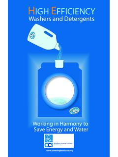
8 So the new design would use Mosfets in the inverter and would operate at above 20kHz to make it inaudible. Third, CDIs used an SCR (silicon controlled rectifier) to discharge the dump capacitor and these are typically rated for an AC supply frequency of 400Hz maximum. While the SCRs will operate at higher frequencies, it is an unspecified condition and it ultimately also sets a limit on the maximum spark rate. That effectively rules out using an SCR in the new design. Fourth, and a rather serious draw- 20 SILICON CHIP ; the circuit of the Multi-Spark CDI can be split into two separate sections, each using an IR2155 self-oscillating half bridge Mosfet driver. ICl and Mosfets Ql & Q2 comprise the 12V DC to 300V DC inverter. IC2 and Mosfets Q6 & Q7 charge and discharge the dump capacitor via the ignition coil primary and provide the multiple spark feature.
9 WARNING! This circuit produces 300V DC which can give you a nasty shock. Do not touch any part of the circuit while it is operating. back this one, some CDI systems would not operate when the battery was low. This meant that while the battery might be able to slowly crank the engine, the CDI's inverter would not start and hence there would be no spark. In other words, just when you most wanted the CDI to work, it would not be on the job. Another factor which limited the inverter operating frequency was the speed of the rectifier diodes. high speed fast recovery diodes were expensive and so, even if the inverter could have run much faster, the stand-ard rectifier diodes could not have handled the high frequency output.
10 Applications While we have addressed all the above disadvantages, the drawback of potential cross-fire remains even though we have reduced the high voltage to 300V. Therefore, we do not rec-ommend using the system on six cylinder and V8 engines unless you can improve the lead dress of the spark plug leads so that each lead is more widely separated from its neighbour. Nor do we recommend using this CDI on any car with an engine management computer. We take the attitude that the factory designed ignition system will always be optimum far the particular car. On the other hand, if you have an older car with factory electronic ignition there is no reason why this CDI system should not be a satisfactory substitute, particularly if the original module has failed and is expensive to replace.