Transcription of A HIGH PERFORMANCE HALF-WAVE DIPOLE ANTENNA
1 A high PERFORMANCE AIRBAND ANTENNA . FOR YOUR ULTRALIGHT / LIGHTSPORT AIRCRAFT. by Dean A. Scott, mfa (revision 3 September 2017). In this article I present a simple, easy to (234 / MHz) * 12 . construct, and easy to mount Inverted V half- wave DIPOLE ANTENNA that will significantly Why are half- and quarter-wave antennas used increase your range and clarity of rather than full-wave? Size. For instance, let's communication in the aircraft radio band when use the unicom airband frequency of compared to rubber-ducky and external MHz. A full-wave ANTENNA would be 7 feet 7- commercial or homemade quarter-wave whip 1/2 long! Try mounting THAT on your plane! antennas. Basic radio frequency (RF) and The HALF-WAVE version is 45-3/4", but that's still ANTENNA theory will be discussed to explain cumbersome. The quarter-wave is 22-7/8" long.
2 Some of the reasons for the design. Much more manageable and thus why it is so offend used. To start, let's define the terms HALF-WAVE and quarter-wave. These refer to the length of a But, doesn't more wire generate more signal? . metal conductor that resonates at a certain Compared to an isotropic ANTENNA (a frequency in the radio spectrum. Specifically, a mathematically prefect ANTENNA that radiates in full-wave ANTENNA is one whose length is the all directions equally), a full-wave has 3 dB (2. same as the distance from one crest to another times) more gain, a HALF-WAVE , dB ( of a radio wave. A HALF-WAVE would be half that times), and a quarter-wave, dB. So, yes, a length (crest to trough) and a quarter-wave full-wave ANTENNA does give the most gain, but would be half that again (crest to zero-crossing at the expense of size.)
3 Point). The length of a radio wave is determined by the equation: Gain is nothing more than a redistribution of a reference radiation pattern such that a certain (c / f) * 12 direction is favored more in receiving and transmitting a signal than another. It's sort of where c is the speed of light, in millions of feet like placing a mirror behind the sun; it becomes per second, and f is the radio frequency, in apparently brighter even though it is radiating megahertz (MHz). the same amount of energy. The other half of the light traveling away from us is simply being In the vacuum of space, electro-magnetic reflected back to us. energy, such as light and radio waves, travels 983,568,960 feet in one second. However, due Another question you may be asking is, Why is to complex interactions with a terrestrial your HALF-WAVE ANTENNA better than the rubber environment (conductors, surrounding ducky or single element whip I already have?
4 Structures, the ground, and other wires connected to an ANTENNA system) this speed is First, the rubber-ducky ANTENNA supplied with effectively reduced to 936 million feet per handheld radios is an inefficient design based second. Divide 936 by 2 and you get the on the low-gain quarter-wave (it's simply 23 or equation for a half wavelength in inches: so of wire coiled into a spring). The reason they are supplied is because they are cheap to (468 / MHz) * 12 make, very robust (it's a bendy spring), and very few people like to carry around a radio that For a quarter wavelength it is: Page 1. has a 2 to 4 foot long anenna sticking up out of Consider this: Your handheld radio with a it! rubber-ducky ANTENNA is only able to spit out not much more than 1 or 2 watts of power due to Second, your typical whip or quarter-wave the ANTENNA 's high Standing Wave Ratio (SWR).
5 ANTENNA requires a ground plane to obtain of 1 to 1:2. This reduces your transmission optimum balance and PERFORMANCE , something range to at best 5 miles and reception range to a tube and fabric ultralight or light-sport aircraft 15 - 20 miles. just really doesn't have. What's a ground plane? It's a flat expanse of metal around 4 feet How about when using an external quarter- in diameter that does what the name implies wave whip ANTENNA ? Much better if the plane simulates earth ground. If not a sheet of metal, has enough metal surface for a ground plane, then at least 4 stiff wires, each around 23 long, and the ANTENNA is properly matched and tuned radiating straight out from the base of the main, to the radio maybe 15 miles transmit and 40. 22-7/8 -long vertical ANTENNA . miles receive. There's just no good way to mount such a Using the ANTENNA design presented here, you monstrousity on any sort of plane, not to should obtain clearly received transmissions mention the increased drag profile.
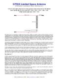
6 Some may from over 60 miles away and be heard by say that the metallic tube frame of a UL/LSA is others 30 miles away (line of sight)! So, let's a good enough ground plane, but RF theory get down to business. and ANTENNA design say otherwise. An aluminum skinned plane is a different story. A. quarter-wave on them works just a well as this PART 1. article's design, so there wouldn't be much ANTENNA ELEMENTS. gained by making the ANTENNA presented here. Figure 1 shows the simple nature of this Third, a HALF-WAVE DIPOLE does not require a Inverted V HALF-WAVE DIPOLE design. It's made ground plane and has 2 dB more gain than a of two stiff wires, 22-7/8 long, forming a 120. whip or rubber ducky. It also doesn't present degree angle. When used on Unicom and air- much of a challenge to mount it compared to a to-air communication frequencies (122 123.)
7 Whip (without a ground plane) and is just as MHz), the element lengths and angle result in a easy to make. 50 ohm terminal impedance, a perfect match for 50 ohm RG-58 coax cable. Fourth and most importantly, this ANTENNA is designed to perfectly match the impedance of Such an even match between the ANTENNA , your radio and coax cable for the best possible cable, and radio means that all possible power transfer of RF energy to and from the radio. It can flow through the system. So, instead of 2. is also designed to counteract the imbalance watts effective power using a rubber ducky with created when the electrically balanced ANTENNA a 4 watt handheld, you'll get the full 4 watts with is connected to the electrically unbalanced coax this design. A mismatch of impedances means cable. power is wasted in the form of heat by the generation of standing waves in the coax cable.
8 Your next question might be, Sounds plausible, but how well does it perform? . Page 2. Figure 1 Dimensions of the Inverted V ANTENNA elements. Any stiff wire that's around 2 mm in diameter Step 1. (12 AWG), such as brass welding rods or even Obtain any sort of hard, dense plastic material coat hangers, can be used. Since coat hangers that's 2 (50mm) wide by 5 (127mm) long by were on hand, that's what I made mine from. 1/4" to 3/8 (6mm 9mm) thick or so. A good source for this would be a common kitchen Step 1 cutting board. Draw a center line dividing the Cut two 25 (634mm) lengths of wire rod. length of the block in half (Figure 2). Step 2. Form a loop with a 3/16 (5mm) inside diameter on one end of each rod using stout needle-nose pliers. Step 3. Cut the rod so it measures 22-7/8 (581mm). from the end of the loop.
9 Step 4. Tape over the looped end and paint the ANTENNA elements to protect from corrosion. Or, if already painted, scrape the paint off the loops, inside and out. Figure 2 Polypropylene or Nylon stock makes a good base for the ANTENNA mounting block. PART 2. FABRICATING THE MOUNTING BLOCK Step 2. Draw a line perpendicular to this that is 1/2". These two ANTENNA elements must be mounted (13mm) below the top edge. On this line mark so that they are held firmly in place at a 120 the locations of the two ANTENNA terminals, one degree angle. This angle is critical! It sets the on either side of the center line and 9/16 . feed point impedance at 50 ohms. The mount (15mm) apart (Figure 3). must keep the elements electrically insulated from each other and all other metallic parts of the system and provide a robust, vibration- resistant way to connect the terminals to a coax cable.
10 The following mounting block fits the bill perfectly. Page 3. Figure 3 Marking the ANTENNA terminals. Step 3. With the center point of a small protractor positioned directly over each terminal point, put a mark on the bottom edge of the block at the Figure 5 Countersinking the two ANTENNA terminal holes 30 degree line. Repeat for the other side. with a wood bit. Step 4 Countersink the BNC connector hole by 1/4". Draw a line connecting each mark to its (6mm) using a 11/16 (17mm) wood bit. respective terminal point to form a 120 degree angle. Drill the ANTENNA terminal holes to size with a 3/16 (5mm) bit and the BNC connector with a Step 5 3/8 ( ) bit (Figure 6). Draw a line 1/2" (13mm) up from the bottom of the block to mark the location for mounting a female panel-mount BNC connector (Figure 4). Figure 6 All holes countersunk first and then drilled to size.