Transcription of A Laboratory Experiment In Linear Series Voltage Regulators
1 Proceedings of the 2001 American Society for Engineering Education Annual Conference & Exposition Copyright 2001, American Society for Engineering Education Session 2526 A Laboratory Experiment in Linear Series Voltage Regulators Jeffrey S. Franzone University of Memphis Abstract Many advanced electronics courses cover Linear Voltage Regulators from the black-box (or IC) perspective. Although this perspective is valid and useful, it doesn t give students much opportunity in a Laboratory setting to deeply investigate the behavior of the major parts of the regulator, its characteristics, and the reinforcement of transistor theory. Many canned Linear Voltage regulator labs favor the quick-and-dirty approach. Students construct a power supply using a Linear Voltage regulator IC, make a few measurements, and observe empirically the stability of the output Voltage with line and load changes.
2 With these labs, students miss the opportunity to see what makes a regulator tick and how different elements of the regulator affect particular regulator characteristics. The Laboratory Experiment presented here tries to address some of the issues that are not covered in depth in common Linear Voltage regulator experiments. They include: Students build a real regulator circuit from discrete transistors. Students actually see the major parts of the regulator and the interaction between each section. Students learn the real meaning of terms such as line and load regulation, % efficiency, and maximum and minimum differential Voltage by observing what factors in the regulator actually influence these parameters. In traditional experiments, constant-current limiting is the only protection scheme shown.
3 This lab not only demonstrates this technique but also foldback-current limiting. The advantage of foldback-current limiting over constant-current limiting is illustrated by an empirical heatsink test. The regulator circuit is first designed with constant-current limiting. The regulator is shorted and students observe that a heatsink is required. Next, the same circuit is constructed with foldback-current limiting. The output is shorted and students observe that a heatsink is not required. Students get to simulate on PSPICE the regulator circuit with constant-current limiting and with foldback-current limiting. The waveforms generated from each circuit clearly emphasize the circuit action and effectiveness of each protection scheme and support the Laboratory results. Page of the 2001 American Society for Engineering Education Annual Conference & Exposition Copyright 2001, American Society for Engineering Education Extensive analysis questions are provided throughout the Experiment to enhance the students problem solving skills.
4 Many questions require detailed explanations using Laboratory measurements, calculations, and simulation results. The Laboratory Experiment has been successfully tested in an advanced solid-state course in community college and is currently taught in an advanced electronics course at the University of Memphis, Engineering Technology Department. Many positive responses were noted from students. Many commented that the depth and breadth of the Experiment was difficult, at times, to digest but very useful in understanding Linear Voltage Regulators and in improving their transistor theory and problem-solving skills. Many really appreciated the practical sections on current protection. I. Introduction The Linear Series Voltage regulator lab Experiment is divided into the following major sections: 1.
5 BACKGROUND 2. OBJECTIVES 3. EQUIPMENT 4. PROCEDURE 5. ANALYSIS QUESTIONS 6. REFERENCES This paper will briefly examine each of these sections providing relevant examples from the actual Laboratory Experiment . The complete Experiment is provided at the end of this paper. Because the Experiment relies heavily on solid state theory and extensive analysis, it is recommended that students should have completed at least one semester of solid state electronics and preferably some limited experience with PSpice for Windows to be successful with this Experiment . The lab Experiment should be completed within six hours, not including a Laboratory report.
6 For a three-hour lab that meets once a week, this Experiment would be a two-week lab. The author recommends assigning PART I, II, and III for the first three hours of lab with PART IV and V for the last three hours. Since the Procedure is divided into separate sections each having its own set of analysis questions, the Experiment can be easily adapted to fit the particular rigor of the instructor. II. BACKGROUND This section discusses many of the important concepts related to Linear Voltage Regulators . The depth of this section is sufficient to be used as lecture material and provides important concepts and formulas necessary to successfully complete and understand the Experiment . Page of the 2001 American Society for Engineering Education Annual Conference & Exposition Copyright 2001, American Society for Engineering Education The basic concepts and terminology necessary for understanding the overall operation of a Series Voltage regulator are discussed first before any detailed analysis.
7 In particular, functional blocks are shown for each major section of a Voltage regulator. This gives students the big picture and helps to emphasize the relationships between each block. Shown below is an excerpt: A Voltage regulator is a device that maintains a constant Voltage across a load even if the load current requirements change. Voltage Regulators are a major building-block in power supplies. (NOTE: in some circuits, the Voltage regulator is the actual power supply.) A Linear Series Voltage regulator contains a control element (usually a transistor) that always operates in the active region, hence the term Linear . The control element is in Series between the unregulated line Voltage and the regulated output Voltage . When the control element is a transistor, it is often referred to as the pass transistor since it passes the required current to maintain a predetermined amount of regulated output Voltage .
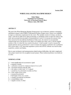
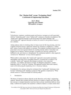
8 The main elements of a Linear Series Voltage regulator include: 1. A control element. 2. A reference Voltage 3. An error detector. 4. A sample circuit. Figure 1 shows the interconnection of these elements. FIGURE 1. The major parts of a Linear Series Voltage regulator.(1) Page of the 2001 American Society for Engineering Education Annual Conference & Exposition Copyright 2001, American Society for Engineering Education The basic operation of the Linear Series Voltage regulator is as follows: An error detector compares a reference Voltage with a sample of the output Voltage . The output of the error detector is fed to a control element. The control element causes the output Voltage to increase or decrease until the sample Voltage equals the reference Voltage .
9 When this occurs, the error Voltage is zero (or some other setpoint value) and the control element is held in a stable state. This keeps the output Voltage relatively constant regardless of the load requirements (within specific limits, of course). A detailed discussion of two Voltage regulator circuit types are introduced; one built around transistors and the other built around an op-amp. Both circuits are used to identify the circuit components that compose each of the major functional blocks of a Voltage regulator and to explain how these blocks interact. In addition, the advantage of an op-amp error-detector versus a transistor error-detector in improving the regulator s transient response is discussed. Next, some important Voltage regulator characteristics are examined such as load and line regulation, percent efficiency, and the relationship between the amount of differential Voltage across the pass transistor and its ability to regulate.
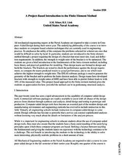
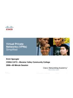
10 Students learn first-hand how to test and measure these characteristics in the Experiment . Finally, the concepts of constant-current limiting and foldback-current limiting are discussed. Each protection scheme is examined in depth, including transfer characteristics and all relevant design formulas. Students have the opportunity to design, test, and observe both protection schemes on the experimental Voltage regulator circuit. Shown below are the transfer characteristics for each protection scheme. Students learn how to use PSpice to simulate these curves and how to interpret them. Page of the 2001 American Society for Engineering Education Annual Conference & Exposition Copyright 2001, American Society for Engineering Education FIGURE 6. Vo vs. IPT(limit) for constant-current limiting protection scheme.