Transcription of A Learning Guide for Model Rocket Launch Systems
1 A Learning Guide for Model Rocket Launch Systems Including: Schematics, Electrical Theory and Study Problems Edited and updated by Ann Grimm . 2012 Estes-Cox Corp. TABLE OF CONTENTS. Model Rocket Launch Systems ..1. Symbols Used in Electrical Circuits ..2. Principles of Electrical Circuits ..3. Electrical Operation of Launch Control Systems ..7. Electrical Mathematics ..8. Electrical Problems Involving Electrical Ignition Systems ..12. Multiple Launcher Circuits ..15. Est. 2811. Copyright 1969, 1976, 1999 Centuri Corporation. All rights reserved.
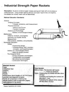
2 Model Rocket Launch Systems . A launching system for Model rockets must perform A small tube ( Launch lug) on the Model fits over the two different jobs. The first job is to hold the Rocket rod, keeping the Rocket straight on the rod. By the before and during Launch . The second job is to ignite time the Model Rocket 's Launch lug leaves the the Rocket 's engine. The Electron Beam Launch rod the Rocket is going fast enough for its Launch Controller pro- fins to provide adequate guidance to keep it moving vides a reliable, portable in the desired direction.
3 Ignition with its own built-in power supply. The second function a Launch system must perform is to provide adequate electrical current to cause To have a safe, pre- engine ignition. The electrical current accomplishes dictable flight, the engine ignition by heating the igniter which pro- Model Rocket must be duces enough heat to cause the solid propellant to held in position before ignite. Launch and guided dur- ing the first fraction of a The igniter must be placed with its bend all the way second of flight until it to the bottom of the nozzle and firmly in contact is going fast enough for with the propellant.
4 The igniter must be held firmly its fins to keep it flying in place with an igniter plug so that the weight of in the proper direction. the micro-clips and wire will not pull it away from The device performing this function should be the propellant. About 90% of Launch failures are designed to aim the Rocket straight up. It may be caused by this rule not being followed. made adjustable so that the Model can be aimed . either vertically or within 30 to any side of vertical to correct for wind conditions. Model Rocket ENGINE. The electrical current delivered by the ignition sys- tem is adequate to heat the igniter, which causes the propellant to ignite.
5 The thermoplastic coating on the end of the igniter helps protect against the igniter shorting out against itself resulting in inade- quate heat reaching the propellant to produce igni- tion. The coating on the igniter also burns when the igniter is heated, producing additional heat for rapid engine ignition. Loose connections will not properly conduct the full electrical current required. 1. The micro-clips which attach to the igniter provide good connections to securely hold the igniter and a SYMBOLS USED IN. good path for the electrical current.
6 If necessary, micro-clips can be cleaned before each flight. ELECTRICAL CIRCUITS. GROUND. WIRE. TWO CONNECTED. WIRES. TWO WIRES NOT. CONNECTED. THREE CONNECTED. WIRES. FOUR CONNECTED. WIRES. TWO WIRES NOT. CONNECTED. SWITCH (OPEN). SWITCH (CLOSED). RESISTOR. ELECTRIC LIGHT. SINGLE DRY CELL. (PRODUCES VOLTS). BATTERY (A BATTERY. IS TWO OR MORE. A blast deflector plate is used to protect the plastic CELLS CONNECTED IN. base of the Porta Pad II from the heat of the rock- SERIES). et's exhaust. 2. PRINCIPLES OF ELECTRICAL CIRCUITS. An electrical current is a flow of electrons.
7 A circuit is These electrons cannot leave the negative terminal the path the electric current follows. The electrons will unless they have a way to flow back into the cell though flow only when a circuit is complete. In effect, electric- the positive terminal. When this pathway exists we say ity must come from some place and have somewhere we have a complete circuit or a closed circuit. If there is to go. Any point beyond which the electron cannot go, a break in the pathway we call it an open circuit. because of a loose connection or unconnected wire, interrupts the path the electrons should follow and hence breaks the circuit.
8 When a circuit is complete, electrons will flow from the negative terminal of a power source through the circuit and return to the same source through its positive terminal. A flashlight dry cell is a common source of electrical power. An electric bulb (such as the pilot bulb for an ignition system ) will not light unless the electricity flows through it. The two terminals of the bulb are shown in the above drawing. The electrons can enter through either termi- nal and leave through the other one. The bulb gives light because electricity flowing through the bulb makes the wire filament inside the bulb get hot.
9 Enough heat is produced to make the bulb incandes- cent (so hot that it glows). Resistance, a kind of electri- cal friction caused by the electrons moving through the filament heats it. The filament glows when enough A dry cell releases electrons by chemical reactions electricity flows through it. occurring within the cell. The construction of a typical dry cell is shown in the illustration above. The black paste electrolyte is made of carbon particles and chemicals. The chemical reactions release electrons which accumulate on the zinc. These electrons travel through the zinc since it is a conductor of electricity.
10 This concentration of electrons on the zinc produces a surplus of electrons at the negative (zinc) terminal of the dry cell. The filament will not glow when the electrical circuit is When a complete circuit is made by connecting the not complete. The most common type of failure in elec- two terminals together with a wire, the electrons that trical bulbs occurs when a portion of the filament melts are concentrated at the negative terminal will flow or breaks, thus making the circuit incomplete. Since the through the wire to the positive terminal. This flow is filament is enclosed inside a sealed glass bulb, once it an electrical current.