Transcription of A New Choke Cookbook for the 160–10M Bands Using Fair …
1 A New Choke Cookbook for the 160 10M Bands Using Fair-Rite #31 (2631803802) and 4-in (2631814002) Toroids 2018-19 by James W. Brown All Rights ReservedIntroduction: Common mode chokes are added as series elements to a transmission line to kill common mode current. The line may be a short one carrying audio or control signals between a computer and a radio, video between a computer and a monitor, noisy power wiring, or feedlines for antennas. This application note focuses on the use of chokes on the feedlines of high power transmitting antennas to suppress received noise, to minimize RF in the shack (and a neighbor s living room) and to minimize crosstalk between stations in multi-transmitter environments. FundamentalsDifferential mode current is the normal transmission of power or other signals inside coax, or between paired conductors. The currents in the two conductors are precisely equal and are out of polarity (that is, flowing in opposite directions at each point along the line).
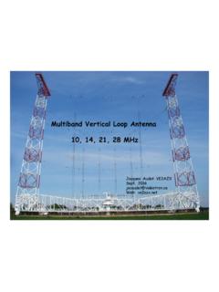
2 Because the current in the two conductors are equal and out of polarity, they do not radiate, nor do they receive. Common mode current is carried on the outside of the coax shield, or as the difference of unequal currents on the two conductors of 2-wire line. A line carrying common mode current acts as antenna for both transmit and receive. Common mode current that couples to the antenna changes the directional pattern of an antenna by filling in the nulls of it s directional pattern. In simple terms, the common mode circuit becomes part of the antenna the part of it that is close to noise sources picks up that noise; and when transmitting, radiates RF that poorly designed equipment will hear as RF interference. Series and Parallel Equivalent Circuits: The fundamental equivalent circuit of a ferrite Choke at radio frequencies simplifies to two parallel resonant circuits, wired in series, as shown in Fig 1. All ferrite chokes have a circuit resonance formed by inductance and resistance coupled from the core and parasitic (stray) capacitance between the two ends of the Choke .
3 LC, RC and CC describe this circuit resonance. For a single turn (a wire goes through the core once), the core itself is the dielectric, and the resonance is typically in the range of 150 MHz. We form a Choke that is useful at HF by winding multiple turns through the ferrite core. Like all inductors, the inductance (LC) is multiplied by the square of the number of turns (N2), and because the resistance is coupled from the core, RC is also multiplied by N2. Parasitic capacitance is both through the core and also between turns, and increases approximately linearly with N. The result is that the resonance movesdown in frequency and the resistance at resonance gets much larger. Some ferrite materials also have a property called dimensional resonance, which is the result of standing waves within the cross section of the ferrite material. Fair-Rite #43 and #61 are NiZn ferrite mixes, and do not exhibit dimensional resonance. Fair-Rite #31, #73, #75, #77, and #78 are MnZn ferrite mixes, and MnZn ferrites do have dimensional resonance.
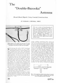
4 LD, RD, and CD Fig 1describe the dimensional resonance (if present). This equivalent circuit describes the impedance of the Choke over a broad frequency range once the values of LD, RD, CD, LC, RC and CC; have been found, they are very approximately constant (the same) for a broad range of frequencies. Fig 2 Our measurements of Choke impedance provide values of ZMAG, RS and XS, as shown in Fig 2, where XS is positive when the impedance is inductive (below resonance), and negative when it is capacitive (above resonance). ZMAG is the magnitude of the impedance, equal to the square root of (RS2 + XS2). These values are different for every frequency, but the plotted (or tabulated) data can be used to find LD, RD, CD, LC, RC and CC. When dimensional resonance is not present, these values can be computed by working backwards from the impedance curves. To a first approximation, RC is simply the value of Z at resonance, LC is the inductance that yields XC well below resonance, and CC is the capacitance that resonates with LC at the measured resonant frequency.
5 At resonance, of course, RC and RS are equal, XS is zero, and the combined reactances of LC and CC is infinitely large. When both resonances are present, the process is significantly more complex. Understanding the Common Mode Circuit: Consider a simple dipole fed with coax. In the common mode circuit, the coax shield becomes part of the antenna, acting as a single wire connected between one side of the center of the antenna and ground. As a common mode circuit element, its VF is near (depending on the diameter of the shield and the dielectric property of the outer jacket). In the common mode circuit, this wire (the coax) has some impedance, (RS + jXS), by virtue of its electrical length, which is different at every frequency. At some frequencies, XS will be positive (inductive), at others it will be negative (capacitive). Why the Emphasis on RS? Because XS of the Choke can be inductive or capacitive, and because the common mode circuit will be inductive at some frequencies and capacitive at others, XS of the Choke can cancel part or all of the Xs of the common mode circuit.
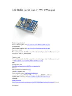
6 This cancellation causes common mode current to increase, which is the opposite of the desired result. But RS of the Choke always adds to the common mode impedance, so a high value of RS always reduces common mode current. Fig 3 shows a Choke added to a feedline that looks capacitive at some frequency of interest. In this example, the capacitive and inductive reactances partially cancel, adding to 4,040 +j 100 . RS and XS values for both Choke and feedline will be different at Feedline 40 j 200 Choke 4,000 +j 300 every frequency, with XS values sometimes adding andFig 3sometimes cancelling, but RS values always adding. In effect, a large Value of RS makes the Choke far less sensitive to line length. [In the common mode circuit, VF is that of the coax shield with its outer jacket, typically on the order of , not the VF of the coax as a transmission line. This VF is also typical of 2-wire line in the common mode circuit.]How Much RS is Needed?
7 From the perspective of both noise suppression and power handling, it has been shown that an RS value of 5,000 is a good starting point for most applications, such as at the feedpoint of a reasonably well-balanced and well matched antenna at power levels below about 600W. More demanding applications (higher power, a badly unbalanced antenna) may require higher choking impedance, and, in general, more is better. Rewinding a Choke to double RS divides the current by 2, which divides the dissipated power by 2 (because power is I2R). Using two identical chokes in series divides the total power by 2 and divides the power dissipated in each Choke by 4. Why chokes Are Needed Without a Choke at the feedpoint, the feedline becomes part of the antenna; if the antenna system, including the feedline, is unbalanced, this causes the feedline to radiate part of transmitted power; when receiving, signal and noise picked up by the feedline is coupled to the antenna.
8 This is most easily understood with coax, where skin effect and proximity effect combine to cause common mode current to flow on the outside of the shield and differentialmode current to flow on the outside of the center conductor and return on the inside of the mode current also flows on parallel 2-wire feedline (where it shows up as the difference between unequal currents in the two conductors) if any part of the antenna system is poorly balanced. An antenna system, can be unbalanced (that is, not symmetrical) by its surroundings unequal heights, ground slope, trees, sloping of the antenna itself, conductive elements of a building or tower very close to it. chokes can be used in series to increase their effectiveness on a single band, or to increase their effective bandwidth, or both. Their combined choking impedance is simply the algebraic sum of their RS and XS values. Baluns and chokes a balun is used to make a transition between balanced and unbalanced circuitry, and can take many forms.
9 Many are not designed to kill common mode current. chokes and Manufactured Antennas My advice is to always use the balun or other matching elements provided with a manufactured antenna (unless you know it to be defective), and to add a common mode Choke between that matching element and the feedline to block common mode current. Rigging chokes To Beam Antennas A Choke is a parallel tuned circuit, and the winding data places the resonance where it is desired for any given antenna. The parallel capacitance is small, typically 4-12 pF; if, for example, we lash coax on either or both sides of the Choke so that it runs tight along the boom, capacitance between the coax and the boom appears in parallel with the Choke , moving its effective range down in frequency, effectively defeating it. Better to rig the Choke by suspending it from the boom, lashing coax to the boom at a single point on each side of the Choke , and minimizing the length of coax that is in contact.
10 Antenna Arrays chokes are most effective when placed at the feedpoint of each element of an array, but care must be taken to make sure that adding the Choke does not change the phasing. A Choke is simply a coiled up length of transmission line, and the electrical length of the feedline to that antenna is increased by the electrical length of the feedline used to wind the Choke . If the feedline and the Choke have the same ZO, shortening the coax by that electrical length is all that is required. But if ZO of the Choke and feedline are different, the chokes must be added to a model ofthe array to study their effect and to determine the degree of shortening required. 75 chokes For 4-Square Transmit Antennas Two possible options are RG302 ( in , solid steel silver coated copper center) and RG179 ( , stranded silver coated copper center). RG302 is close enough in size to RG400 that recommendations for RG400 can be used. Grant, KZ1W, sent me some RG179, and I wound chokes on the same test toroids.