Transcription of A New Solution for Harmonics Generated by VSDs
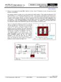
1 A New Solution for HarmonicsGenerated by Variable Speed DrivesIn addition to its harmonic mit-igating capabilities, this widespectrum harmonic filter helpsprotect a VSD from transientovervoltages caused by capacitorswitching and other fast changingloads. It is suitable for virtuallyany application involving a VSDor similar 3-phase, 6-pulse diodebridge rectifier load. Harmonic ProblemsThe front-end diode bridge recti-fiers of 3-phase, 6-pulse static powerconvertors (ac-dc), such as those foundin variable speed drives, are considerednonlinear because they draw current ina non-sinusoidal manner. The currentharmonics they generate are definedby the following formula:h= np 1 Where:h= the Harmonics Generated n= any integer (1, 2, 3, etc.)p= the rectifier pulse numberA simple 6-pulse rectifier (p =6) is shown in Figure 1. Withoutany harmonic treatment, the totalharmonic current distortion (THID)of this rectifier would be in the100-140% range with the predomi-nant Harmonics being the 5thand7th.
2 The 11th, 13th, and other higherorders are also present but at lowerlevels. In the example shown inFigure 1, the 5thharmonic currentis about 75% of the fundamental(60Hz) current and the 7thnearly60%. This means that a rectifier ofthis configuration, which draws100A of 60Hz current, will alsodraw 75A of the 5thharmonic cur-rent and 60A of the distribution systems carry-ing a heavy nonlinear load compo-nent will often experience problemscaused by excessive harmonic cur-rents. Problems that arise include: Power factor correction capaci-tor failures due to overloadingand/or system resonance he need for harmonic mitigating devices isgrowing because of the rapid increase in vari-able speed drive (VSD) usage in industrial andcommercial applications and the corresponding growthin harmonic-related problems. A new state-of-the-artpassive universal harmonic filter (UHF) is designed toenhance the conversion of ac power to dc power within aVSD or other equipment with a 3-phase, 6-pulse diodebridge rectifier front-end.
3 Tony Hoevenaars, , MIRUS International Inc., Toronto, OntarioTEditor s Note:This article focuses on aspecific new product fromMIRUS International this article is manu-facturer-oriented, based uponthe information we observedwhen the product was dis-played at our recent PowerQuality 99conference, PQMagazine believes this prod-uct deserves to be presentedto our readers so that theymay investigate its claims ontheir own. DECEMBER 1999 Overheating cables, transformersand other distribution equipmentreducing their life span High voltage distortion (typical-ly in the form of flat-topping),especially when operating onweak sources such as emergencygenerators False tripping of circuit breakers Premature failure of rotatingequipment (motors, generators,etc.) Misoperation or component fail-ure in PLCs, computers or othersensitive loads Existing Methods ofHarmonic Treatment forVSDsThere are several methodsavailable for treatment of VSDharmonics.
4 Ac input reactors(either 3 or 5% impedance) arethe most commonly used treat-ment. They have a relatively lowcost but are only moderatelyeffective in reducing harmoniccurrent distortion (see Figure 2and Table 1for typical values).The high impedance of ac inputreactors helps protect the drivefrom transient overvoltagescaused by capacitor switchingand/or fast changing loads butthey can often introduce trouble-some voltage drops at the rectifierinput. Some VSDs are equippedwith a dc link reactor that isslightly more effective at reducingharmonic currents than the acreactor, and it does not cause anac voltage drop. The dc link reac-tor, however, is somewhat lesseffective than the ac reactor inovervoltage protection. Conventional tuned LC or trapfilters, as their name implies,require tuning to a specific har-monic frequency. Usually, 6-pulserectifier loads are tuned to themost predominant harmonic the5th.
5 Their effectiveness is limited,however, unless multiple tunedelements are incorporated toremove the 7thand other higherorder Harmonics . They are proneto problems such as importationof Harmonics from upstream non-linear loads and the introductionof a leading power factor. By treating a wider spectrum ofharmonics, low-pass filters aremore effective than tuned filters,but are also more they address some of theissues associated with tuned fil-ters, they are not , their large seriesinductor necessitates the use of alarge capacitor bank to compen-sate for voltage drops. Thesecapacitors create a leading powerfactor that may cause excitationcontrol and voltage fluctuationproblems with multipulsed systems, thedrive manufacturer will phase shiftbetween multiple front-end recti-fiers to cancel Harmonics . Some18 and 24-pulsed systems canachieve THID levels of < 8%, butthey require a large footprint andare quite expensive.
6 The applica-tion of phase shifting transformerscan be a very cost-effectivemethod of harmonic treatmentwhere multiple 6-pulse VSDs arein operation. A quasi 12-pulsescheme ( , cancellation of 5thand 7thharmonics) can be createdby phase shifting one VSD againsta second similar VSD. The 18 and24-pulse schemes require threeand four VSDs, filters treat harmonicsby measuring the level of harmon-ic current present in the systemand injecting currents of oppositepolarity to cancel them performance can beachieved but reliability is some-times an issue and their high costhas limited their use. Due to thedynamic characteristics associatedwith detection and treatment, fastchanging conditions may not beadequately addressed. The Universal HarmonicFilter vs. OtherConventional PassiveFiltersThe UHF is a purely passiveseries connected device, whichcan be installed at the input ofany 3-phase, 6-pulse diode bridgerectifier to dramatically reduce itsinput current Harmonics .
7 Its revo-lutionary design achieves cancel-lation of all the major harmoniccurrents Generated by the rectifier,resulting in THID of <8% andoften as low as 5%. This meetsIEEE std 519 harmonic currentlimits for all but the weakest ofsupply sources. The unique fea-ture of the UHF is its 3-phasereactor design consisting of multi-ple windings on a common mag-netic core. This reactor allows forthe use of a much smaller capaci-tor bank without sacrificing filterperformance or introducing unac-ceptable voltage drops. Capacitivereactive power is typically 3-4xlower than that of conventionalfilters. This is significant inreducing cost and space require-ments. Moreover, it preventspower system interaction prob-lems that often result from a lead-ing power factor. The large capacitor banksfound in both tuned and low-passfilters present a capacitive reac-tance to the system, especiallyunder light loads.
8 This is a bene-ficial feature where inductiveloads require a compensatingreactance to improve a low dis-placement power factor. But inmost VSD applications, displace-ment power factor is close tounity even though overall powerfactor may be low due to the har-monic content in the for inductive loadsis usually not necessary and, infact, can cause problems, espe-cially when supplied by an emer-gency standby generator. Toaddress this issue, some filter manufacturers offermechanisms for switching out the capacitors underlight loads, which increases cost and under no load conditions, the capacitive reac-tance of the UHF is so low that switching out thecapacitors is concern with tuned filters is that unlessthey incorporate a detuning reactor in series with thesupply feeder, they can easily be overloaded byattracting Harmonics from upstream sources. Thedetuning reactor will introduce a voltage drop at thedc bus as load is applied to the VSD.
9 The multiplewinding configuration of the UHF, on the otherhand, prevents the attraction of Harmonics fromupstream sources without introducing an excessivevoltage drop as VSD load increases. The filtering effectiveness of a tuned filter isdependent upon the amount of Harmonics present atuntuned frequencies as well as the residual at thetuned frequency. To obtain performance better than15% THID, multiple tuned branches are oftenrequired. Low-pass filters achieve <12% THID butrequire relatively large capacitor banks. Even largercapacitors are required if further reduction in THIDis desired. The UHF reduces current distortion to<8% over the entire operating range and typicallyachieves near 5% THID at normal operating levels. Simulation of Harmonic FilterPerformanceAs previously mentioned, many of today s VSDsare equipped with either ac line reactors or dc linkchokes to reduce harmonic current simulation allows us to compare thesesolutions with the UHF.
10 The circuit diagram shownin Figure 1was used to simulate a 5kW, 380V 6-pulse diode bridge rectifier. Five different harmonictreatment schemes were analyzed as follows:Scheme 1 No harmonic treatment Scheme 2 With 3% ac line reactorScheme 3 With 8 mH dc link chokeScheme 4 With both ac line reactor and dc link choke Scheme 5 With universal harmonic filterThe chart in Figure 2plots the THID for eachscheme over the full operating range of the no harmonic treatment, THID ranged fromnearly 180% at extremely light loading to 140% atfull load. The reactors implemented in Schemes 2, 3and 4 reduced the THID by approximately the sameamount. THID ranged from 100% near no load to 30-Figure 3-phase, 6-pulse diode bridge rectifier withno harmonic Harmonic Current Distortion through computersimulation of a 5kW, 6-pulse rectifier with various forms of pas-sive harmonic bus voltage through computer simulation of a 5kW,380V 6-pulse rectifier with various forms of passive at full load.


