Transcription of A Practical Approach for Modelling Submarine Subsystem ...
1 347 Submarine Institute of Australia Science, Technology & Engineering Conference 2013 PAPER 12 A Practical Approach For Modelling Submarine Subsystem Architecture In SysML Paul Pearce ASC Pty. Ltd. Osborne, South Australia Sanford Friedenthal SAF Consulting Fairfax, Virginia USA Abstract This paper outlines a Practical design Approach for Submarine subsystems using a model-based systems engineering (MBSE) methodology. At the core of this Approach is a system model that provides a precise, consistent, traceable and integrated description of the Submarine Subsystem architecture. The system model is used to support the flow-down of requirements from the Submarine missions to system, to Subsystem and to component specifications. The system model is defined in the OMG Systems Modeling Language (OMG SysML ) and implemented in an established commercial SysML graphical Modelling tool.
2 The MBSE Approach is based on a combination of industry best practice and the Practical experiences of deploying MBSE within a Submarine design team. This Approach is being used by the design team at both whole-of- Submarine and Subsystem levels of design. This paper will elaborate on the application of MBSE to Submarine Subsystem architecture and focus on Modelling artefacts that provide direct benefit during the early stages of achieving a balanced Submarine design. This paper will discuss a number of important topics associated with building a system model that is intended to evolve from an initial concept design over the lifecycle of the Submarine . Of particular interest is the reference architecture scaffolding used to support capabilities such as variant Modelling , and the integration of Failure Modes & Effects Analysis (FMEA) within the system model. Keywords- Submarine Design; System Architecture; Model-Based Systems Engineering; System Modelling ; SysML I.
3 INTRODUCTION A. Complex System Design A conventional military submarine1 contains more than forty subsystems covering a wide range of functions; from combat and weapons handling to services that provide cooling and hydraulics. These subsystems are highly integrated and collocated within the confines of a single pressure hull. Undesirable behaviour and properties often emerge once the Submarine is operational. Of course, it is unwise to wait until a Submarine is built to discover such deficiencies, as 1 A conventional Submarine is powered by batteries that are routinely recharged by diesel generators. For this paper, a modern conventional Submarine is defined as built from the late-1980s, characterised by greater use of integrated computer technology, compared with earlier generations of submarines. modifications to completed submarines are extremely costly and can deprive the nation of an important asset.
4 Computer Modelling is increasingly used during the earliest design phases (when the cost of change is relatively low) to define a robust system architecture and predict the emergent behaviour and properties of a design. Design integrity, consistency and traceability can be enhanced further by integrating different computer models of the same system. The practice of using integrated computer models to govern the specification, design, evaluation and support of a system throughout its lifecycle is called Model-Based Systems Engineering (MBSE). B. Model-Based Systems Engineering The last decade has seen a rise in the application of MBSE across several industries, most notably in defence, but also in aerospace and rail. As a result, many different MBSE methodologies have been published by a range of practitioners, utilising a variety of different processes, models and tools [1]. A holistic multi-disciplinary system model is central to most MBSE methodologies, which can be expressed in SysML [2].
5 The aim of this paper is to outline an MBSE Approach for specifying and designing Submarine subsystems in SysML during the early design phases. This Approach has been developed by ASC Pty. Ltd. to support the architecting of Submarine subsystems for Australia s Future Submarine as outlined in the 2013 Defence White Paper [3]. This paper is organised into three sections; requisite background concepts, the method itself, and finally a number of further considerations. C. For The Practitioner This paper is written for the practicing engineer who is looking for examples of how to apply MBSE and SysML to the design of complex subsystems . Indeed, the Approach outlined in this paper is designed to be used by domain engineers with minimal exposure to systems engineering theory or practice (let alone SysML). The importance of making the system model accessible to individuals who are not systems engineers is a recurring theme in this paper.
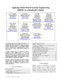
6 348 Submarine Institute of Australia Science, Technology & Engineering Conference 2013 II. BACKGROUND This section introduces a number of important concepts to prepare the reader for subsequent sections of this paper where the MBSE methodology is discussed. These concepts underpin a design process framework that is applied at each level of design, recursively down the left-hand side of the systems engineering V lifecycle, from the whole-of- Submarine to its subsystems and their components. This framework is aligned with technical systems engineering processes defined in ISO-15288 [4] and Modelling activities defined by the Object-Oriented Systems Engineering Method (OOSEM) [5]. The creation and development of this framework to support early stage Submarine design is explained in [6]. Essentially a matrix was defined with ISO-15288 processes and OOSEM activities on opposing axes. The resulting points of intersection found between processes and activities in this matrix were then grouped into the four process areas illustrated in Fig.
7 1. In this figure, the rectangles with rounded corners represent processes and the rectangles with square corners represent products. The Requirements Development and Architectural Design process groups involve the development of the system specification and architecture respectively and are where MBSE has been most widely applied in industry. The Technical Evaluation group of processes define engineering analyses and trade-studies that are used to evaluate system requirements and design artefacts. Finally, at the whole-of- Submarine level of design, the Synthesis group of processes define traditional ship design practices, including initial Submarine sizing and estimation, spatial design and integration (using CAD), hydrostatic design, hydrodynamic design and the design of the Submarine hull structures. At the Subsystem level of design, Synthesis processes comprise initial estimation of equipment properties, preliminary system schematics and sizing calculations.
8 Design synthesis at the Subsystem level is discussed later in this section. Each concept described in this section is first introduced using terms familiar to most systems engineers, and then a corresponding implementation of that concept will be defined in SysML. The concepts that are discussed include: Black-Box Specification Requirements Traceability Abstraction Inheritance Architecture Variant Modelling Model Organization Design Synthesis A. The Black-Box Specification During the development of system requirements, it is useful to view the system-of-interest as a black-box ; in terms of its interfaces with the external environment and other entities, and how it is expected to function and perform within that context. A black-box definition does not assume or expose the internal structure, behaviour or properties of the system. This Approach delineates the definition of the specification (what the system is expected to do) from any particular solution (how the system could be implemented).
9 A black-box specification of a system should as a minimum define the following features; functions to be performed by the system; key properties or measures of performance for that system, and; external interfaces. These features result from, and are further refined by, requirements elicitation and analysis tasks performed for the system-of-interest, usually over several design iterations. Figure 1. Specification & Design Process 349 Submarine Institute of Australia Science, Technology & Engineering Conference 2013 A black-box specification can be defined in SysML using a block element. A block defines features that map directly to system functions (as operations), properties (as system characteristics such as weight with values) and interfaces (as ports). B. Requirements Traceability A system specification can be viewed as an organised collection of textual requirements for that system. Beyond a certain threshold, specifications with a large number of requirements benefit from being managed in an electronic repository.
10 This is certainly the case for Submarine Subsystem specifications, each of which can contain more than 1000 requirements. In such a tool, each requirement, in addition to its unique identifier and text, can be annotated with attributes such as performance bounds, priority, verification method and compliance status. Textual requirement statements can be defined in SysML using requirement elements. These elements contain fields for the requirement text and its unique identifier. Duplicating requirements between the requirements management tool and the system Modelling tool can be avoided since most established SysML Modelling tools support the synchronisation of requirement elements with their counterparts in an external requirements management tool repository, including traceability information. By representing requirements in the system model, it is possible to link these elements with their corresponding feature in a black-box specification.