Transcription of A Practical Guide to ‘Free Energy’ Devices
1 A Practical Guide to free energy Devices Devices Part 17: Last updated: 23rd August 2009 Author: Patrick J. Kelly Dealing with the Vehicle Computer When an mpg. improving device such as an electrolyser is fitted to a vehicle, the result does not always produce better mpg. figures. Older vehicles which are fitted with a carburettor will see an immediate improvement. This is not the case for more recent vehicles which come with computer control of the fuel sent to the engine. When an electrolyzer is attached to the engine, it causes the fuel burn inside the cylinders to be greatly improved, with a corresponding improvement in engine performance. Unfortunately, the fuel computer is expecting the same amount of unburnt oxygen to come out of the engine, and when it doesn t detect it, the computer increases the fuel flow rate in an attempt to get back to it s normal, inefficient method of running.
2 That action cancels the mpg improvement produced by the electrolyzer unless something is done to adjust the operation of the computer. In the most simple terms, most vehicles which have an Electronic Control Unit ( ECU ) to control the fuel flow are fitted with one of two types of exhaust sensor. The majority have a narrowband sensor while the remainder have a wideband sensor. The ideal mix of air to fuel is considered to be to 1. A narrowband sensor only responds to mixtures from about to 1 through to 1. The sensor operates by comparing the amount of oxygen in the exhaust gas to the amount of oxygen in the air outside the vehicle and it generates an output voltage which moves rapidly between volts where the mixture is too lean, and volts when it passes below the to 1 air/fuel mix point where the mixture is too rich (as indicated by the graph shown below). The ECU increases the fuel feed when the signal level is volts and decreases it when the signal voltage is volts.
3 This causes the signal voltage to switch regularly from high to low and back to high again as the computer attempts to match the amount of too lean time to the amount of too rich time. A simple control circuit board can be added to alter the sensor signal and nudge the fuel computer into producing slightly better air/fuel mixes. Unfortunately, there is a severe downside to doing this. If, for any reason, the fuel mix is set too high for an extended period, then the excess fuel being burnt in the catalytic converter can raise the temperature there high enough to melt the internal components of the converter. On the other hand, if the circuit board is switched to a mix which is too lean, then the engine temperature can be pushed high enough to damage the valves, which is an expensive mistake. 1 2 Over-lean running can occur at different speeds and loads. Joe Hanson recommends that if any device for making the mix leaner is fitted to the vehicle, then the following procedure should be carried out.
4 Buy a type K thermocouple with a 3-inch stainless steel threaded shank, custom built by ThermX Southwest of San Diego. This temperature sensor can measure temperatures up to 1,800 degrees Fahrenheit (980 degrees Centigrade). Mount the thermocouple on the exhaust pipe by drilling and tapping the pipe close to the exhaust manifold, just next to the flange gasket. Take a cable from the thermocouple into the driver s area and use a multimeter to show the temperature. Drive the vehicle long enough to reach normal running temperature and then drive at full speed on a highway. Note the temperature reading at this speed. When a leaner mix is used, make sure that the temperature reading under exactly the same conditions does not exceed 180 degrees Fahrenheit (100 degrees Centigrade) above the pre-modification temperature. David Andruczyk recommends an alternative method of avoiding engine damage through over-lean fuel/air mixtures, namely, replacing the narrowband oxygen sensor with a wideband sensor and controller.
5 A wideband oxygen sensor reads a very wide range of Air/Fuel ratios, from about 9 to 1 through 28 to 1. A normal car engine can run from about 10 to 1 (very rich) to about to 1 (pretty lean). Maximum engine power is developed at a mix ratio of about to 1. Complete fuel combustion takes place with a mix of about to 1, while the mix which gives minimum exhaust emissions is slightly leaner than that. Unlike narrowband sensors, wideband sensors need their own controller in order to function. There are many of these units being offered for sale for retro-fitting to existing vehicles which have just narrowband oxygen sensor systems. David s personal recommendation is the Innovate Motorsports LC-1 which is small, and uses the very reasonably priced LSU-4 sensor. This wideband controller can be programmed. Most controllers have the ability to output two signals, the wideband signal suitable for running to a gauge or new ECU, plus a synthesised narrowband signal which can feed an existing ECU.
6 The trick is to install a wideband sensor, with the LC-1 controller and then reprogram it to shift the narrowband output to achieve a leaner mix as shown here: Actual Air/Fuel Mix Wideband Output Original Narrowband Output Shifted Narrowband Output 9 to 1 9 to 1 Mix is too Rich Mix is too Rich 10 to 1 10 to 1 Mix is too Rich Mix is too Rich 11 to 1 11 to 1 Mix is too Rich Mix is too Rich 12 to 1 12 to 1 Mix is too Rich Mix is too Rich 13 to 1 13 to 1 Mix is too Rich Mix is too Rich 14 to 1 14 to 1 Mix is too Rich Mix is too Rich to 1 to 1 Mix is too Rich Mix is too Rich to 1 to 1 Mix is too Lean Mix is too Rich 15 to 1 15 to 1 Mix is too Lean Mix is too Rich to 1 to 1 Mix is too Lean Mix is too Lean 16 to 1 16 to 1 Mix is too Lean Mix is too Lean 18 to 1 18 to 1 Mix is too Lean Mix is too Lean This system allows you to set the narrowband toggle point very precisely on an exact chosen air/fuel ratio. This is something which it is nearly impossible to do accurately with a circuit board which just shifts a narrowband oxygen signal as you just do not know what the air/fuel ratio really is with a narrowband sensor.
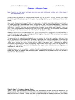
7 However, for anyone who wants to try adding a circuit board to alter a narrowband sensor signal to produce a leaner mix on a vehicle, the following description may be of help. It is possible to buy a ready-made circuit board, although using a completely different operating technique, from the very reputable Eagle Research, via their website: where the relevant item is shown like this: This unit generates a small voltage, using a 555 timer chip as an oscillator, rectifying the output to give a small adjustable voltage which is then added to whatever voltage is being generated by the oxygen sensor. This voltage is adjusted at installation time and is then left permanently at that setting. Eagle Research also offer for sale, a booklet which shows you how to build this unit from scratch if you would prefer to do that. I understand that at the present time, the purchase price of this device is approximately US $50, but that needs to be checked if you decide to buy one.
8 Alternatively, instructions for building a suitable equivalent circuit board are provided later on in this document. If you wish to use a circuit board with a narrowband oxygen sensor, then please be aware that there are several versions of this type of sensor. The version is indicated by the number of connecting wires: Those with 1 wire, where the wire carries the signal and the case is ground (zero volts) Those with 2 wires, where one wire carries the signal and the other wire is ground. Those with 3 wires, where 2 (typically slightly thicker) wires are for a sensor heater, and 1 for the signal while the case is ground. Those with 4 wires (the most common on current model cars), where there are 2 (slightly heavier) for the sensor heater, 1 for the signal , and 1 for the signal ground. (Sensors with 5 wires are normally wideband Devices .) Look in the engine compartment and locate the oxygen sensor. If you have difficulty in finding it, get a copy of the Clymer or Haynes Maintenance Manual for your vehicle as that will show you the position.
9 We need to identify the sensor wire which carries the control signal to the fuel control computer. To do this, make sure that the car is switched off, then For 3 and 4 wire sensors: Disconnect the oxygen sensor wiring harness, Set a multimeter to a DC voltage measurement range of at least 15 volts, Turn on the ignition and probe the socket looking for the two wires that provide 12 volts. These are the heater wires, so make a note of which they are, Shut the ignition off, and reconnect the oxygen sensor. 3 The two remaining wires can now be treated the same as the wires from a 2-wire sensor, one will carry the sensor signal and one will be the signal ground (for a single wire sensor, the signal ground will be the engine block). Jesper Ingerslev points out that the Ford Mustang built since 1996 has 2 oxygen sensors per catalytic converter, one before the converter and one after. Some other vehicles also have this arrangement.
10 With a vehicle of this type, the circuit board described here should be attached to the sensor closest to the engine. Find a convenient place along the wires. Don t cut these wires, you will cut the sensor wire here at a later time, but not now. Instead, strip back a small amount of the insulation on each wire. Be careful to avoid the wires short-circuiting to each other or to the body of the vehicle. Connect the DC voltmeter to the wires (the non- heater wires). Start the engine and watch the meter readings. When the engine is warmed up, if the oxygen sensor is performing as it should ( no engine check lights on), the voltage on the meter should begin toggling between a low value near zero volts and a high value of about 1 volt. If the meter reading is going negative, then reverse the leads. The black multimeter lead is connected to the signal 'ground' (zero volts) and the red lead will be connected to the wire which carries the signal from the sensor.