Transcription of a Voltage-to-Frequency Converter 3 V/5 V Low …
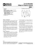
1 FUNCTIONAL BLOCK *FEATURESS ynchronous OperationFull-Scale frequency Set by External System Clock 8-Lead SOT-23 and 8-Lead MSOP Packages3 V or 5 V OperationLow Power: 3 mW (Typ)Nominal Input Range: 0 to VREFTrue 150 mV Capability Without Charge Pump VREF Range: V to VDDI nternal V Reference1 MHz Max Input FrequencySelectable High Impedance Buffered Input Minimal External Components RequiredAPPLICATIONSI solation of High Common-Mode VoltagesLow-Cost Analog-to-Digital ConversionBattery MonitoringAutomotive SensingGENERAL DESCRIPTIONThe AD7740 is a low-cost, ultrasmall synchronous Voltage-to-Frequency Converter (VFC).
2 It works from a single V to V or V to V supply consuming mA. The AD7740 is available in an 8-lead SOT-23 and also in an 8-lead MSOP package. Small package, low cost and ease of use were majordesign goals for this product. The part contains an on-chip Vbandgap reference but the user may overdrive this using anexternal reference. This external reference range includes full-scale output frequency is synchronous with the clocksignal on the CLKIN pin. This clock can be generated with theaddition of an external crystal (or resonator) or supplied from aCMOS-compatible clock source.
3 The part has a maximuminput frequency of 1 an analog input signal that goes from 0 V to VREF, the out-put frequency goes from 10% to 90% of fCLKIN. In buffered mode,the part provides a very high input impedance and accepts arange of V to VDD V on the VIN pin. There is alsoan unbuffered mode of operation that allows VIN to go from V to VDD + V. The modes are interchangeable usingthe BUF AD7740 (Y Grade) is guaranteed over the automotivetemperature range of 40 C to +105 C. The AD7740 (K Grade)is guaranteed from 0 C to 85 HIGHLIGHTS1.
4 The AD7740 is a single channel, single-ended VFC. It isavailable in 8-lead SOT-23 and 8-lead MSOP packages, and is intended for low-cost applications. The AD7740 offers considerable space saving over alternative The AD7740 operates from a single V to V or Vto V supply and consumes typically mA when theinput is unbuffered. It also contains an automatic The AD7740 does not require external resistors and capaci-tors to set the output frequency . The maximum outputfrequency is set by a crystal or a clock.
5 No trimming or cali-bration is The analog input can be taken to 150 mV below GND fortrue bipolar The specified voltage reference range on REFIN is V to the supply voltage , V/5 V Low Power, SynchronousVoltage-to- frequency Converter *Protected under Patent # 6,147, C Document Feedback Information furnished by Analog Devices is believed to be accurate and reliable. However, no responsibility is assumed by Analog Devices for its use, nor for any infringements of patents or other rights of third parties that may result from its use.
6 Specifications subject to change without notice. No license is granted by implication or otherwise under any patent or patent rights of Analog Devices. Trademarks and registered trademarks are the property of their respective owners. One Technology Way, Box 9106, Norwood, MA 02062-9106, : 2001 2016 Analog Devices, Inc. All rights reserved. Technical Support AD7740 SPECIFICATIONS K, Y Versions1 Parameter2 MinTypMaxUnitTest Conditions/CommentsDC PERFORMANCEI ntegral NonlinearityCLKIN = 32 kHz3 of Span4 Unbuffered Mode, External Clock at CLKINCLKIN = 1 MHz of SpanUnbuffered Mode, Crystal at CLKINCLKIN = 32 kHz3 of SpanBuffered Mode, External Clock at CLKINCLKIN = 1 MHz of SpanBuffered Mode, Crystal at CLKINO ffset Error 7 35mVUnbuffered Mode, VIN = 0 V 7 35mVBuffered Mode.
7 VIN = VGain Error of SpanOffset Error Drift3 20 V/ CGain Error Drift3 4ppm of Span/ CPower Supply Rejection Ratio3 55dB VDD = 5% (5 V) 65dB VDD = 10% ( V)ANALOG INPUT, VINN ominal Input Span0 VREFV 150 mV Overrange ModeInput Current810 AUnbuffered Mode, VIN = V, REFIN = V5100nABuffered Mode, VIN = V, REFIN = VREFERENCE VOLTAGEREFIN5 Nominal Input Impedance31k See Pin Function DescriptionReference Drift3 50ppm/ CLine Rejection3 75dB VDD = 5% (5 V)Line Rejection3 60dB VDD = 10% ( V)Reference Noise ( Hz to 10 Hz)3100 V p pFOUT OUTPUTN ominal frequency Span fCLKIN to fCLKINHzVIN = 0 V to VREF.
8 See Figure 2 LOGIC INPUTS (CLKIN, BUF)3 CLKINI nput Frequency321000kHzFor Specified PerformanceInput High voltage , = 5 V 5%Input High voltage , = V 10%Input Low voltage , = 5 V 5%Input Low voltage , = V 10%Input Current 2 AVIN = 0 V to VDDPin Capacitance310pFBUFI nput High voltage , = 5 V 5%Input High voltage , = V 10%Input Low voltage , = 5 V 5%Input Low voltage , = V 10%Input Current 100nAPin Capacitance310pFLOGIC OUTPUTS (FOUT, CLKOUT)3 Output High voltage , Sourcing 200 A6. VDD = 5 V 5%Output High voltage , Sourcing 200 A6.
9 VDD = V 10%Output Low voltage , Sinking mA6 POWER (Normal Mode) = VDD, VIL= GND. Unbuffered ModeIDD (Normal Mode) = VDD, VIL= GND. Buffered ModeIDD (Power-Down)30100 APower-Up Time330 sExiting Power-Down (Ext. Clock at CLKIN)NOTES1 Temperature range: K Version, 0 C to +85 C; Y Version, 40 C to +105 C; typical specifications are at 25 by design and characterization, not production = Max output frequency Min output this pin is bidirectional, any external reference must be capable of sinking/sourcing 400 A in order to overdrive the internal logic levels apply to CLKOUT only when it is loaded with one CMOS at VDD = V is also possible with degraded unloaded.
10 IDD increases by CL VOUT fFOUT when FOUT is loaded. If using a crystal/resonator as the clock source, IDD will vary depending on the crystal/resonatortype (see Clock Generation section).Specifications subject to change without C 2 (VDD = V to V, V to V, GND = 0 V, REFIN = V; CLKIN = 1 MHz; All specifications TMIN to TMAX unless otherwise noted.)AD7740 REV. C 3 (VDD = V to V, V to V, GND = O V, REFIN = V)Limit at TMIN, TMAXL imit at TMIN, TMAXP arameterVDD = V to VVDD = V to VUnitConditions/CommentsfCLKIN3232kHz minClock Frequency11 MHz maxtHIGH:tLOW40:6040:60minClock Mark/Space Ratio60:4060.