Transcription of a2.7 V to 5.5 V RGB-to-NTSC/PAL Encoder with …
1 A V to V RGB-to-NTSC/PAL Encoder with Load Detect and Input Termination Switch AD723. FEATURES or combined for composite video (CV). All outputs are avail- Low Cost, Fully Integrated Solution for ntsc /PAL able separately and optimized for driving 75 loads. Active Composite and Y/C (S-Video) Outputs termination is used for lower power consumption. Current Output Drives 75 Loads A smart load detect feature powers down unused outputs and DC-Coupled: Supports TV Load Detect can be used to monitor the continuing presence or absence of No Large AC-Coupling Capacitors at Output Self-Power-Down of Unloaded Output Drivers an external TV. This enables plug-and-play operation.
2 In addition, Triple Switch to Enable RGB Termination a logic controlled triple switch at the input solves the applica- Integrated Delay Line and Auto-Tuned Filters tions problem of differing load conditions when an RGB monitor Y-Trap to Eliminate Cross Color Artifacts is disconnected. When an RGB monitor is not present, the R, 3 V Supply Operation: Low Power G, and B terminations are enabled by the user. This solution < 100 mW: Composite Active (Typical) ensures no loss of video bandwidth when the RGB monitor is < 150 mW: S-Video Active (Typical) in operation. <1 A: Power-Down Current In PC applications, flicker filter support is provided by the APPLICATIONS graphics controller, which has direct access to memory.
3 Under- TV Out for Personal Computers/Laptops scan compensation, necessary for uses other than video or Digital Cameras DVD, is supported through choice of RGB output clocks and Set-Top Boxes sync intervals. Video Games An optional luminance trap (YTRAP) provides a means of Internet Appliances reducing cross color artifacts due to subcarrier frequency infor- PRODUCT DESCRIPTION mation in the Y signal. The AD723 is a low cost RGB-to-NTSC/PAL Encoder that The AD723 is available in a 28-lead TSSOP package and is converts analog red, green, and blue color component signals capable of operation from supplies of V to V. into their corresponding luminance and chrominance signals for display on an ntsc or PAL television.
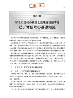
4 Luminance (Y) and Chrominance (C) signals are available individually for S-video, FUNCTIONAL BLOCK DIAGRAM. CURRENT OUTPUT DRIVERS. 8 FSC CLK WITH SMART LOAD DETECT. TRIPLE INPUT. TERMINATION. LUMINANCE. RIN DC Y 4-POLE LUMA 4-POLE Y. CLAMP LPF DELAY LINE LPF. RT LUMA. Y TRAP. GND TRAP. CSYNC COMPOSITE. RGB-TO-YUV CV. GIN DC ENCODING U 4-POLE. CLAMP MATRIX LPF. GT. BALANCED CHROMINANCE. GND MODULATORS. BURST 4-POLE C. LPF. BIN DC V 4-POLE. CLAMP LPF. BT. GND YSET. BURST SIN COS. GAIN SET CSET. TERM RESISTORS. AD723 CVSET. QUADRATURE FSC. 4 FSC DECODER. HSYNC BURST. SYNC. VSYNC SEPARATOR CSYNC. STND CE TV DETECT. REV. 0. Information furnished by analog devices is believed to be accurate and reliable.
5 However, no responsibility is assumed by analog devices for its use, nor for any infringements of patents or other rights of third parties One Technology Way, Box 9106, Norwood, MA 02062-9106, which may result from its use. No license is granted by implication or Tel: 781/329-4700 World Wide Web Site: otherwise under any patent or patent rights of analog devices . Fax: 781/326-8703 analog devices , Inc., 2000. AD723 SPECIFICATIONS (VS = 3, TA = 25 C, using 4 FSC synchronous clock unless otherwise noted. Signal inputs terminated with 75 . Outputs configured in active termination mode, 75 external load.). Parameter Conditions Min Typ Max Unit SIGNAL INPUTS (RIN, GIN, BIN).
6 Input Amplitude Full-Scale 714 mV p-p Clamp Level 400 mV. Input Resistance RIN, GIN, BIN 1 M . Input Capacitance 5 pF. TERMINATION SWITCH CHARACTERISTICS. (RT, GT, BT). Input Capacitance VIN = 0 V 6 pF. Switch On Resistance VIN = 0 V . LOGIC INPUTS. (STND, SA, CE, TERM, SYNC, 4 FSC). Logic LO Input Voltage 1 V. Logic HI Input Voltage 2 V. Logic LO Input Current (DC) A. Logic HI Input Current (DC) A. VIDEO OUTPUTS. Luminance (Y). 3 dB Bandwidth, ntsc Mode ntsc MHz PAL MHz Gain Error Direct Input Termination + %. Switch Input Termination %. Gain Nonlinearity %. Sync Amplitude ntsc 218 262 362 mV. PAL 230 277 385 mV. DC Black Level ntsc 450 mV. PAL 450 mV. Chrominance (C).
7 Burst Amplitude ntsc 185 250 315 mV p-p PAL 190 251 320 mV p-p Chroma Level Error1 Switch Input Termination 4 %. Chroma Phase Error2 3 Degree Color Burst Width ntsc s PAL s Chroma/Luma Time Alignment 19 ns Chroma Feedthrough RGB = 0 40 mV p-p DC Black Level ntsc 661 mV. PAL 608 mV. Composite (CV). Gain Error Direct Input Termination + %. Switch Input Termination %. Gain Error wrt LUMA Direct Input Termination %. Differential Gain Error wrt CRMA %. Differential Phase Error wrt CRMA Degree DC Black Level ntsc 456 mV. PAL 440 mV. Luminance Trap (YTRAP) Output Resistance k . LOGIC OUTPUT (TVDET). LO Output Voltage V. HI Output Voltage V. POWER SUPPLIES. Operating Voltage Range Single Supply V.
8 Current Consumption Quiescent No External Loads Present 16 19 mA. Composite Output Connected3 75 Load, Active Termination, 30 39 mA. S-Video Inactive S-Video Output Connected3 75 Load, Active Termination, 41 49 mA. Composite Output Inactive Power-Down Current A. NOTES. 1. Difference between ideal and actual color-bar subcarrier amplitudes. 2. Difference between ideal and actual color-bar subcarrier phase. 3. Current consumption is larger in standard termination mode. Current values shown for 50% average picture level. Larger current consumption possible for other levels. Specifications subject to change without notice. 2 REV. 0. AD723. ABSOLUTE MAXIMUM RATINGS* PIN CONFIGURATION.
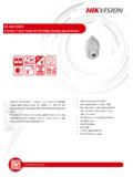
9 Supply Voltage, AVDD to AGND .. 6 V. Supply Voltage, DVDD to DGND .. 6 V STND 1 28 AGND. AVDD to DVDD .. V to + V SA 2 27 YSET. AGND to DGND .. V to + V CE 3 26 Y. Inputs .. DGND to DVDD + V TERM 4 25 AVDD1. Internal Power Dissipation .. 800 mW RIN 5 24 CSET. Operating Temperature Range .. 40 C to +85 C GIN 6. AD723. 23 C. Storage Temperature Range .. 65 C to +125 C BIN 7 TOP VIEW 22 AVDD. Lead Temperature Range (Soldering 60 sec) .. 300 C AGND 8 (Not to Scale) 21 YTRAP. RT 9 20 CV. *Stresses above those listed under Absolute Maximum Ratings may cause perma- nent damage to the device. This is a stress rating only; functional operation of the GT 10 19 CVSET.
10 Device at these or any other conditions above those indicated in the operational BT 11 18 TVDET. section of this specification is not implied. Exposure to absolute maximum rating TGND 12 17 4 FSC. conditions for extended periods may affect device reliability. DVDD 13 16 VSYNC. DGND 14 15 HSYNC. THERMAL CHARACTERISTICS. 28-lead TSSOP package: JA = C/W. Thermal Resistance measured on SEMI standard 4-layer board. ORDERING GUIDE. Temperature Package Package Model Range Description Option AD723 ARU 40 C to +85 C 28-Lead TSSOP RU-28. AD723 ARU-REEL 40 C to +85 C 28-Lead TSSOP RU-28. AD723-EVAL Evaluation Board CAUTION. ESD (electrostatic discharge) sensitive device.