Transcription of AB-6763 Specifications/Instructions ACTIVAL™ - …
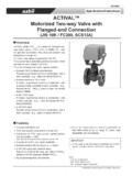
1 AB-6763 ACTIVAL Motorized Two-Way Valve with Flanged-End Connection for High Differential Pressure Application(JIS 10K-FC200, SCS13A) Specifications/Instructions 1 2007-2017 Azbil Corporation All Rights Reserved. Overview ACTIVAL Model VY51_ _J is a series of motorized two-way rotary valves, DN15 to DN150, with flanged-end connection. The valve and actuator are integrated in a single unit. The valve body rating corresponds to JIS 10K. The actuator has a reversible synchronous motor, which operates at a low voltage of 24 V AC. There are following four control signals available. Nominal 135 feedback potentiometer Provides proportional control in combination with a DDC controller. ( , Infi lex GC Model WY5111) Nominal resistance 135 input Provides proportional control in combination with a proportionally controlled electric controller.
2 ( , Neostat Model TY900_Z, insertion type Thermostat Model TY9800) 4-20 mA DC input Provides proportional control in combination with a DDC controller. ( , Infi lex GC Model WY5111, Model R35/R36) 2-10 V DC input Provides proportional control in combination with a DDC controller. ( , Infi lex AC Model WY5117) Features Applicable for the high differential pressure applications such as controlling the bypass fl ow is controlled inside the valve to prevent over pressure drop, leading to cavitation erosion 1 Mechanism of cavitation erosion resistanceNotes: - AHU: Air Handling Unit - DDC: Direct Digital Control - JIS: Japanese Industrial Standards Compact and lightweight Valve and actuator integrated in a single unit Conforms to IP54 (dust-proof, splash-proof) Can be installed in : Waterproof connectors are required to assure IP54.
3 A variety of control input signals available Durable actuator with low power consumption 2 10 V DC output with feedback signal Only for 4-20 mA DC input type (Model VY513_) and 2 10 V DC input type (Model VY514_) Modifi ed linear fl ow characteristics Valve is applicable for high differential pressure, large Cv value, high rangeability, and low If you want to use this product combined with a third party's controller, please contact Azbil : Pictures of DN25 and DN125 are posted. The shape differs depending on the valve PrecautionsPlease read instructions carefully and use the product as specified in this manual. Be sure to keep this manual nearby for quick reference. Restrictions on UseThis product was developed, designed, and manufactured for general air conditioning not use the product in a situation where human life may be at risk or for nuclear applications in radiation controlled areas.
4 If you wish to use the product in a radiation controlled area, please contact Azbil when the product is used in the following applications where safety is required, implementation of fail-safe design, redundant design, regular maintenance, etc., should be considered in order to use the product safely and reliably. Safety devices for protecting the human body Start/stop control devices for transportation machines Aeronautical/aerospace machines For system design, application design, instructions for use, or product applications, please contact Azbil Corporation bears no responsibility for any result, or lack of result, deriving from the customer s use of the Design LifeIt is recommended that this product be used within the recommended design recommended design life is the period during which you can use the product safely and reliably based on the design specifications.
5 If the product is used beyond this period, its failure ratio may increase due to time-related deterioration of parts, etc. The recommended design life during which the product can operate reliably with the lowest failure ratio and least deterioration over time is estimated scientifically based on acceleration tests, endurance tests, etc., taking into consideration the operating environment, conditions, and frequency of use as basic parameters. The recommended design life of this product is 10 recommended design life assumes that maintenance, such as replacement of the limited life parts, is carried out properly. Refer to the section on maintenance in this and Cautions WARNINGA lerts users that improper handling may cause death or serious injury.
6 CAUTIONA lerts users that improper handling may cause minor injury or material Notifies users that specific actions are prohibited to prevent possible danger. The symbol inside graphically indicates the prohibited action. (For example, the sign on the left means that disassembly is prohibited.) Instructs users to carry out a specific obligatory action to prevent possible danger. The symbol inside graphically indicates the actual action to be carried out. (For example, the sign on the left indicates general instructions.) WARNING When handling or transporting any heavy product (more than 18 kg), carefully move the product with a handtruck or the like, or with 2 or more lifting or accidental dropping of the product may result in injury or product damage.
7 CAUTION Provide a circuit protector ( , a fuse or circuit breaker) for the power to do so may cause a short circuit leading to fire or device failure. Do not freeze this so may damage the valve body and cause leakage. When piping this product, be sure there is no foreign matter in the foreign matter remains in the pipes, the product may break down. Install, wire, and use this product under the conditions specified by this to do so may cause fire or device failure. Use full face gaskets for flat face to do so may damage the flanges or cause leakage outside of the valve. When installing this product, hold it in the proper position and securely fasten it to the tightening or improper installation position may damage the Model NumbersModel VY51_ _J0_ _ _ is the model for the valve and actuator integrated into a single model number label is attached on the model numberActuator/valveActuatorValveDescrip tionControl signalRating/materialTypeFixedValve sizeCvVY51 Motorized two-way rotary valve1 Nominal 135 feedback potentiometer (F motor type)2 Nominal 135 resistance input (E motor type)34 20 mA DC with 2 10 V DC feedback signal42 10 V DC input with 2 10 V DC feedback signal3 JIS 10K-FC200 (for chilled/hot water)
8 With cavitation erosion resistant mechanism4 JIS 10K-SCS13A (for chilled/hot water) with cavitation erosion resistant mechanismJIEC IP54 (dust-proof, splash-proof) , with standard torque type terminal block (Applicable valve sizes: DN15 to DN 125)IEC IP54 (dust-proof, splash-proof) , with high voltage type terminal block (Applicable valve size: DN150)0 Fixed012DN15 (1/2 ) , Cv: (1 ) , Cv: (1 ) , Cv: 10040DN40 (1 ) , Cv: 16041DN40 (1 ) , Cv: 25050DN50 (2 ) , Cv: 40060DN65 (2 ) , Cv: 65080DN80 (3 ) , Cv: 95101*DN100 (4 ) , Cv: 180121*DN125 (5 ) , Cv: 234151*DN150 (6 ) , Cv: 350* When JIS 10K-FC200 (Model VY51_3) is selected according to the rating and material of the valve, 101, 121, or 151 can be selected by specifying the valve size and Cv.
9 CAUTION After installation, make sure no fluid leaks from the valve-pipe piping may cause fluid leakage outside of the valve. Do not put a load or weight on this so may damage the product. Installation and wiring of the actuator must be performed by personnel qualified to do instrumentation and electrical in installation or wiring may cause fire or electric shock. Before wiring or maintenance, be sure to turn off the power to this to do so may result in electric shock or device failure. All wiring must comply with applicable codes and there is a danger of fire. CAUTION Use crimp terminals with insulation for connections to the product to do so may cause short circuit leading to fire or device failure.
10 Tighten the terminal screws with the specified tightening of the terminal screws may cause fire or overheating. After wiring or maintenance, be sure to reattach the terminal to do so may result in electric shock. Do not carelessly touch this product when it is used to control hot so may result in burns, because the product reaches a high :- IEC: International Electrotechnical CommissionAB-67634 zOptionsItemModel numberSpecificationPower transformerAT72-J1 Primary voltage100 V AC, 200 V AC, or 220 V ACSecondary voltage23 V ACPower frequency50 60 HzWaterproof connector*183104346-003 Applicable wireDia. 7 9 mmAuxiliary switch*283174063-101 Number of auxiliary switches2 Max. applied voltage, current30 V DC, 100 mA*3 (Inductive load includes inrush current.)