Transcription of ABB drives Reference manual Grounding and …
1 ABB drivesReference manualGrounding and cabling of drive systemsPEPE~~PEU2V2W2U1V1W1M3 ~ L1L2L3L1L2L3 PEPE~~U2V2W2U1V1W1M3 ~ PEL1L2L3L1L2L3 Reference manualGrounding and cabling of drive systems3 AFY61201998 Rev CENEFFECTIVE: 2013-03-25 2013 ABB Oy. All Rights Reserved. 5 Table of contents1. Introduction to the manualContents of this chapter .. 7 Applicability .. 7 Target audience .. 7 Purpose of this manual .. 7 Contents of the manual .. 8 Related documents .. 8 Literature references on EMC .. 8 Literature and standards on bearing currents .. 8 Standard references on cabling .. 9 Terms and abbreviations .. 92. BasicsContents of this chapter .. 11 Objectives of Grounding .. 11 Attenuating motor shaft and frame voltages .. 12 Bearing currents .. 12 Grounding structure .. 13 Buildings without ground planes .. 13PE (protective ground) versus FE (functional ground) .. 143. cabling of drive systemsContents of this chapter.
2 15 General .. 15 Connecting the drive to the supply power network .. 15 Transformer .. 15 Grounded secondary (TN and TN-S systems) .. 15 Ungrounded secondary (IT systems) .. 16 Recommended input power cable types .. 16 Connection diagram of a shielded cable .. 17 Input connection in high-power supply systems .. 17 Busbar system .. 17 Cable bus system (parallel single-core cables) .. 18 Connecting the drive to the motor .. 19 Decreasing bearing current risk .. 19 General instructions .. 19 Recommended motor cable types .. 19 Sufficient conductivity of the protective conductor .. 20 Calculating the cross-sectional area .. 20 Sufficient shield conductivity to suppress emissions .. 21 Motor cable types for limited use .. 21 Not allowed motor cable types .. 21 Diagrams of recommended connections .. 22 Grounding the motor cable shield at the motor end .. 23 Motor cabling of high-power drives .. 24 Potential equalization between the motor and driven equipment.
3 246 Connection diagram .. 25 Potential equalization of the motor frame and the terminal box .. 26 Example drive system cabling with potential equalization .. 27 Motor cable connections to be avoided .. 28 Asymmetrical four-core cables .. 28 Connection diagrams .. 28DC drives .. 30 Selecting and connecting control cables .. 31 When to use shielded cables .. 31 Connecting the cable shield .. 31 Description .. 31 Instructions .. 32 Analog and digital signals in separate cables .. 32 Signals allowed to be run in the same cable .. 32 Relay cable type .. 32 Serial communication (eg, fieldbus) .. 32 cabling and insulation of pulse encoders .. 32 Galvanic isolation .. 32 Common mode inductors .. 33 Routing the cables .. 33 Grounding diagram of an AC drive system .. 34 Grounding diagram of a DC drive system .. 354. Interference couplingContents of this chapter.
4 37 Common impedance coupling .. 38 How to decrease coupling via a ground loop .. 38 Capacitive coupling .. 39 How to decrease capacitive coupling .. 39 How to decrease stray capacitance .. 39 Inductive coupling .. 40 How to decrease inductive coupling between circuits .. 40 How to decrease mutual inductance .. 40 How to get extra disturbance suppression .. 40 Electromagnetic coupling .. 41 How to protect against electromagnetic waves .. 41 Further informationProduct and service inquiries .. 43 Product training .. 43 Providing feedback on ABB drives manuals .. 43 Document library on the Internet .. 43 Introduction to the manual 71 Introduction to the manualContents of this chapterThis chapter gives a description of the manual is applicable for low voltage AC and DC drive systems. The drive system in this manual consists of the supply transformer, input power cable of the drive, the variable speed drive (frequency converter), motor cable and motor.
5 Target audienceThis manual is intended for people who are involved in variable speed drive system installations and of this manualThe purpose of this manual is tell you the Grounding and cabling principles of variable speed drive systems. The guidelines help you to fulfill the personnel safety, electromagnetic compatibility (EMC) and reliability requirements of the : The installation must always be designed and made according to applicable local laws and regulations. ABB does not assume any liability whatsoever for any installation which breaches the local laws and/or other regulations. Furthermore, if the recommendations given by ABB are not obeyed, the drive may experience problems that the warranty does not Introduction to the manualContents of the manualThe manual tells about the Grounding and cabling principles of variable speed drive systems, and gives examples for correct cabling and Grounding practices.
6 It also includes a short description of interference chapters of this manual are briefly introduced tells about Grounding structures that are needed for interference-free operation of variable speed drive systems and basics of protecting motor bearings. cabling of drive systems gives examples of correct cabling and Grounding of variable speed drive coupling tells principally about different ways of interference coupling. It also gives guidelines on how to decrease the documentsSee the drive hardware manuals for specific instructions of each drive type. For other products, see their manuals. Literature references on EMCI nterference-free electronics by Dr. Sten Benda. Ordering number ABB 3 BSE 000877R0001, ISBN 91-44-3140-9, ISBN 61000-5-2:1997. Electromagnetic compatibility (EMC) Part 5: Installation and mitigation guidelines Section 2: Earthing and cablingTechnical guide No. 3. EMC compliant installation and configuration for a power drive system (3 AFE61348280 [English]) Literature and standards on bearing currentsHigh Frequency Bearing Currents in Low Voltage Asynchronous Motors New Reason for Bearing Current Damage in Variable Speed AC drives by J.
7 Ollila, T. Hammar, J. Iisakkala, H. Tuusa. EPE 97. The European Conference on Power Electronics and Applications 8 10 September 1997 Trondheim, Norway. Pages to the Bearing Currents in Medium Power Variable Speed AC drives by J. Ollila, T. Hammar, J. Iisakkala, H. Tuusa. Proceedings of the IEEE IEDMC in Milwaukee, May 1997. Evaluation of Motor Power Cables for PWM AC drives by John M. Bentley, Patric J. Link. IEEE Transactions on Industry Applications, 1997, Volume 33, pages 342 Electric Bearing Currents in Adjustable Speed Drive Systems by Patric J. Link. IEEE IAS Pulp & Paper Conference Portland, ME, USA June 61000-5-2:1997. Installation and mitigation guidelines Earthing and cablingIEC 60034-17:2002 Rotating electrical machines, Cage induction motors when fed from converters Application guideIEC 60034-25:2004. Rotating electrical machines Guide for the design and performance of cage induction motors specifically designed for converter supplyLaakerivirta ja sen minimoiminen s dettyjen vaihtovirtak ytt jen moottoreissa by Ilkka Erkkil.
8 Automaatio 1999 14. Technical Report No. 2 Motor Shaft Voltages and Bearing Currents under PWM Inverter Operation. to the manual 9 GAMBICA/REMA User guide No. 3. Installation Guidelines for Power Drive Systems. guide No. 5. Bearing currents in modern AC drive systems (3 AFE64230247 [English]) Standard references on cablingEN 50174-2:2009. Information technology cabling installation Part 2: Installation planning and practices inside buildingsIEC 60364-4-44:2007. Low-voltage electrical installations Part 4-44: Protection for safety Protection against voltage disturbances and electromagnetic disturbancesTerms and abbreviationsTerm/AbbreviationExplanatio nEMCE lectromagnetic compatibilityEMIE lectromagnetic interferenceFEFunctional earthing ( Grounding ). Earthing a point or points in a system, installation or equipment, for purposes other than electrical safety. IEC 60050-195 (195-01-13) earthing ( Grounding ).
9 Earthing a point or points in a system, installation or equipment for purposes of electrical safety. IEC 60050-195 (195-01-11) of an electromagnetic barrier that separates the shielded circuits from the external sources of EMI or confines the EMI effects to the shielded volume. An electromagnetic barrier is a closed surface of shields and other elements made up to prevent electromagnetic waves from propagating in space or along conductors or to confine the propagating. The barrier can be made of metal conductively coated equipment cases interconnecting cable shields filters or surge arresters on conductors that go through the shield or mesh waveguides working below the cutoff frequency at ventilation openings. In a protected system, the barrier is everywhere so impervious that guided and space waves of EMI sources outside the barrier do not degrade the performance of the protected earth (ground). This term has been replaced with Introduction to the manualBasics 112 BasicsContents of this chapterThis chapter tells about Grounding structures that are needed for interference-free operation of variable speed drive systems and basics of protecting motor of groundingTraditional Grounding is based on electrical safety.
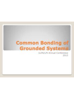
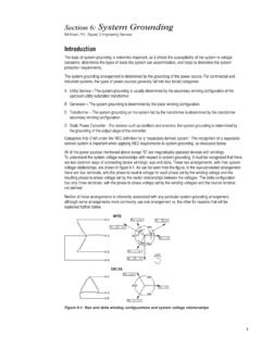
10 It ensures personnel safety in all circumstances and limits material damages due to electrical faults. For interference-free operation and reliability of the drive system, more profound methods are needed: high-frequency Grounding and equipotential ground planes on building floor, equipment enclosure and circuit board BasicsAttenuating motor shaft and frame voltagesProper cabling and Grounding strongly attenuates motor shaft and frame voltages that can cause high-frequency bearing currents and lead to premature bearing replacements. Bearing currentsThis drawing shows schematically two types of bearing currents: high-frequency circulating current (5) and shaft Grounding current (7). INVERTERMOTOR CABLEMOTORGEARLOAD4736 Shaft groundingcurrent24 High frequencyshaft voltageHigh frequencyframe voltage7 Commo n modevoltage pulse213565 High frequencycirculating current-DC+DC11 High frequencyc ommo n modecurrentPE-currentDriveMotor cableMotorGearLoadBasics 13 Grounding structureA well structured Grounding begins with ground electrodes which are connected to each other reliably to form a network.