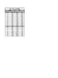
Transcription of Absolute Pressure Gauge Pressure - Zenith Fuel …
1 NOTES The spark-ignited engine (Otto Cycle) is a constant air- fuel ratio engine, and although the volume of air inside the cylinders re-mains constant, the density of air ( MAP or Vacuum) varies ac-cording to the throttle position. Absolute Pressure : Absolute Pressure is a Pressure using a scale with zero starting at zero atmospheric Pressure (PSIA) Gauge Pressure : Gauge Pressure is a Pressure using a scale with zero starting at atmospheric Pressure (PSIG) Zero PSIG = PSIA hg. The Zenith Electronic Engine Management System (ZEEMS) con-trols both fuel delivery and the governor/throttle with an inte-grated throttle body and electronic control unit design. Each control system is described separately, but in actual operation, control of fuel and throttle happen simultaneously. NOTES fuel System: Review of a gasoline carburetor system will aid in understanding the ZEEMS fuel system operation.
2 Carburetors, mechanical fuel injection systems and electronic fuel injection systems all perform the same basic functions; however, the methods incorporated to perform these functions differ. The fundamental purpose of any fuel system is to measure the incoming air and mix the appropri-ate amount of fuel with it under all engine operating conditions. The carburetor performs three main functions. These functions are: a. To deliver a mixture of gas and air in a ratio that suits each condition of engine operation. b. To atomize the gasoline as it enters the intake manifold. c. To control the volume of air / fuel delivered in response to throttle position and engine operation condition. In reality, each engine operating condition requires a circuit or mechanism to be designed into and attached to the gasoline car-buretor to ensure that the engine will operate without hesitation or flat-spot and give maximum power with the optimum fuel economy within the levels of emissions for that model and year of engine design.
3 The ZEEMS fuel injection system is based on the speed-density concept. The ECU uses engine RPM, IMAP, IAT and ECT to calculate the fuel required for a specific engine operat-ing condition. By using RPM, IMAP, IAT and ECT to calculate in-take manifold air density, the ECU calculates the correct fuel re- NOTES In the near future when exhaust catalysts are needed to make the required emission standards, an exhaust gas oxygen sensor (EGOS) will be included to make further corrections to fuel re-quirements to enhance exhaust catalyst efficiency. Once the required fuel delivery is calculated, fuel under Pressure from the fuel pump is injected via the fuel injector into the air stream above the throttle plate. The fuel injector acts as a simple on/off solenoid. The volume of fuel flow is determined by varying the length of time the injector is held open by the ECU. This is known as pulse width modula-tion (PWM) and is measured in milliseconds.
4 The injector is pulsed each time a spark plug fires. Each time a plug fires and that cylinder is in the power stroke, another cylinder is in the in-take stroke. Between each spark plug firing, the ECU calculates the fuel required for the next engine event based on the informa-tion provided to the ECU. ! " ! # $ % % $ % % & $ % " NOTES NOTES ZEEMS uses two different types of injectors, depending on the type of fuel . For gasoline, a pintle valve and seat injector is used. When the gasoline injector coil is energized, a pintle is lifted from a fuel seat to allow the flow of pressurized gasoline. The LPG injector incorporates a flapper valve design. When the injector coil is energized, a flat disc is lifted from the fuel seat al-lowing LPG to flow. Gasoline Injec-Propane Injec-Ignition control & timing: On engines that are equipped with a CKP (crankshaft position) sensor, ZEEMS utilizes the RPM, MAP and temperature sensors signals to calculate fuel rate, and to switch the ignition coil thus eliminating the need for a separate spark control module.
5 To give optimum engine power and exhaust emissions two timing advance curves are engineered for each engine application, one for gasoline and another for propane. On dual/ fuel units, the ECU stores both timing curves and controls the timing to suit the fuel being used. On engines that are equipped with distributors ZEEMS has the capacity to control ignition timing , but this depends on the type of OEM ignition system utilized. As with DIS engines, two timing advance curves are engineered into the system. Some units are equipped with a vacuum delay valve between the throttle body and the vacuum advance unit. This provides a momentary NOTES For optimum engine performance and emissions, the ECU will automatically increase the fuel injection rate on gasoline or pro-pane under engine acceleration and during cold starts This is factory NOTES Note: When installing or replacing the inline pump, make sure that the outlet is connected to the terminal end of the pump.
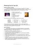
6 Make sure that the electrical terminals are installed correctly ( large terminal +12 Volts) or the pump will run backwards. ' # fuel injectors are sensitive to contaminants and require filters in the 20 30 micron range. The gasoline systems uses a 20 micron filter. fuel Pump: To supply gasoline to the injector, ZEEMS utilizes a high capacity (16 gallons / hour) fuel pump. Depending on the machine, this will be an inline or intank pump. INLINE GASOLINE fuel PUMP INLET OUTLET Gasoline fuel Fil- NOTES Pressure Regulator: A Pressure regulator, mounted in the throttle body and down-stream of the injector, maintains the gasoline fuel Pressure to ap-proximately 10 psi. Unused fuel is returned to the fuel tank via a return line from the Pressure regulator. When checking gasoline Pressure , make sure the engine is running. Note: Return fuel should exit to the vapor space in the tank.
7 Note: Gasoline caps need to be vented. Gasoline Regulator ZEEMS COMPONENT LOCATIONS Gasoline System ! " #$% & ' ( ) & NOTES Governor Operation: ZEEMS has an innovative state - of - the - art throttle / governor system. This is a drive by wire system that gives significant torque and drivability improvements to the spark ignited engine that the diesel has enjoyed for many years. The spark ignited engine is a constant air fuel ratio engine, en-gine speed is maintained by controlling air flow via a throttle fly. The ZEEMS drive by wire system has full authority of the throt-tle fly and will seek to maintain a set engine speed regardless of engine load which significantly improves performance of the spark ignited engine over a conventional speed limiting governor system. An electric actuator controls the throttle plate. With no voltage ap-plied to the throttle / governor control, the throttle is closed against the throttle stop.
8 The mechanical throttle stop is set at an RPM below normal idle, typically around 500 RPM. The ECU receives a voltage input from either a multi position speed switch mounted on the dash, or throttle pedal driven po-tentiometer With 12 volts DC applied, the throttle is wide open. The ECU con-trols the throttle opening by pulsing the voltage between 0 and 12 volts to obtain an average applied voltage and opening. Throttle Actuator Throttle Actuator NOTES When the operator calls for an increase/decrease in speed, the ECU compares the current engine RPM to the desired engine RPM. The ECU applies a pulse width to the throttle actuator to increase/decrease engine RPM accordingly. Once the desired RPM is obtained and a demand for increased/decreased engine load is called for, the ECU will command the actuator to open or close the throttle fly without operator interference maintaining a constant engine RPM.
9 The ECU governs engine RPM with a proportional-integral-derivative (PID) controller. This type of controller allows much faster governor response than conventional mechanical gover-nors. Control to idle or maximum engine RPM occurs very rapidly with minimum RPM undershoot/overshoot. For optimum ma-chine performance under all operating conditions, the governor is calibrated specifically for each engine application. Because no two machines are exactly alike, the ECU has the ability to learn and adjust the throttle stop for improved idle quality and low speed governing. After a period of extended, un-interrupted engine idle at normal operating temperature, the ECU will reprogram idle parameters to correct idle speed and im-proved decelerations. After the initial factory installation, it is un-likely that the ECU will need to learn its base setting. Note: The throttle plate mechanical idle stop setting must still be checked and adjusted.
10 Check particular engine specifications. : If any electrical failure to the throttle control occurs, the throttle will return to the mechanical idle stop position. If for any reason engine RPM exceeds the maximum limits, fuel delivery is interrupted. The gasoline fuel pump or LPG lock-off will disengage in 2 4 seconds if the ignition key is on and there is no secondary igni-tion pulse to the ignition coil. There is no need to depress the throttle pedal to set the choke or provide fuel for cold start. Depressing the throttle pedal has no effect until the engine is running. The ECU opens the throttle to a predetermined position for starting. NOTES 1. Liquid propane, at approximately 100 psi (70 F), flows from the tank through the service line . The hydrostatic relief valve is located in the service line fitting. Its function is to relieve Pressure at 450 psi that could occur if the liquid in the service line were to be heated by a fire, etc.