Transcription of Abstract - John-Tom
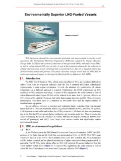
1 Abstract McCalley, Christian Talbot. Experimental Investigations of Liquid fueled Pulsejet Engines. (Under the direction of Dr. William L. Roberts). Various sizes of pulsejets are used to study the effects of heavy liquid fuels like kerosene and military grade JP-8. A hobby scale pulsejet, commercially available from Bailey Machine Services (BMS), is used with gasoline to verify data acquisition techniques, and attempts are made to use kerosene to fuel the jet to prove the viability of using kerosene to power pulsejet engines. A large valved pulsejet, predicted to deliver 25 lbs of thrust, is designed to be used with kerosene for initial testing to prove the feasibility of using such a propulsion device for personal troop transport. A 25 cm valveless pulsejet is designed, fabricated, and tested using propane, gasoline, and kerosene to determine if such an engine is practical for propelling a small, high speed Unmanned Aerial Vehicle (UAV) for military application.
2 Temperatures, average and instantaneous combustion chamber pressure, sound pressure levels and jet operating frequencies were recorded at various fuel flow rates. EXPERIMENTAL INVESTIGATIONS OF LIQUID fueled PULSEJET ENGINES By Christian Talbot McCalley A thesis submitted in partial fulfillment of the requirements for the degree of Masters of Science Mechanical Engineering North Carolina State University Raleigh, NC 2006 Approved by: Dr. William L. Roberts Dr. Terry Scharton Chair of Supervisory Committee Co-Chair of Supervisory Committee Dr. Ronald O. Scattergood Dr. Andrey V. Kuznetsov Committee Member Committee Member ii Biography The author was born Christian Talbot McCalley of King George, Virginia in November of 1980, son of Richard and Saranne McCalley. He is the youngest son with a brother and sister, Michael and Marjory. He was raised on a farm in the county of King George, where he developed an interest in two-stroke motorcycle racing engines which eventually led to an amateur career in auto racing.
3 He was enrolled at Fredericksburg Christian School, a private institution, from the time he was 5 years old until graduating in 1999. While at high school, McCalley spent summers working for his father at Rappahanock Forge Inc. where he developed various fabrication skills. After high school he attended North Carolina State University in Raleigh, North Carolina where he earned a Bachelor of Science degree in Mechanical Engineering in May of 2004 graduating with high honors. While at North Carolina State, McCalley pursued his auto racing career as a driver and a mechanic amassing six different series championships. He accredits his racing experience with giving him the tools needed in the world of research and development to apply the theory and lessons learned in the classroom. After graduating, McCalley decided to further his education and entered the Master of Science Program for Mechanical Engineering where he received his degree under the direction of Dr.
4 William L. Roberts. iii Acknowledgements The author would like to acknowledge his advisor, Dr. William L. Roberts, for his guidance and support, and defense committee, Dr. Terry Scharton, and Dr. Andrey Kuznetzov, and Dr. Ronald Scattergood, for their aid and counsel. The author would also like to thank the machinists in the Mechanical and Aerospace Engineering Department, Rufus Skip Richardson and Mike Breedlove, for precise and elegant fabrication of many complex parts. The author is grateful for the backing from his associates at AERL; Rob Ordon for his help and work that preceded that of the authors, Tiffany Berry, Sean Danby, Carlye Rojas and Peter Nyahoro. Most importantly the author desires to acknowledge Jesus Christ, his Lord and Savior. Just as important the author would like to thank his parents, Richard and Saranne McCalley, for their wisdom, support, and unconditional love.
5 Along with his parent the author wishes to recognize his siblings Mike McCalley and Midge McGovern for their love and friendship. iv Table of Contents List of 1. Background and Related Objectives of the 2. Experimental Apparatus and Pulsejets Bailey Machine Service 50 cm Valved 25 lb Thrust 25 cm Pulsejet Basic 25 cm Component Porous Jet Spike Inlet Flow Enlarged Combustion Chamber Ignition Fuel Injection Fuel Flow Digital Flow Pressure Kulite Strain Gage DPX Piezoelectric Crystal Pressure Mercury Water Sound Oscilloscope ..37 Thrust Linear Linear Coil Weather Startup 50 cm Valved Table of Contents v 25 cm Valveless Propane 25 cm Valveless Liquid 25 cm Valveless Short Electronic 3.
6 Investigations with the 50 cm Valved Pressure Transducer Kerosene fueled 4. Achievements with the 25 cm Valveless Attaining Operation with a Hydrocarbon Effect of Fuel Injector Attaining Operation at a Shorter Attaining Operation on a Heavy Liquid Operation on Operation on Operating on Kerosene at a Shorter Difficulties with Operating on 5. Proof of Concept Experiments with a Forward Flow The Spike Inlet Flow 6. Frequency Review of Helmholz Resonators and Sixth Wave Effect of Filtering Pressure and Sound Data with Investigations Using Fast Fourier Transfer Frequency Effects of 7. Fuel Flow Rate Dependency ..94 Fuel Flow Rate and Pressure Fuel Flow Rate and Sound Pressure 8. Comparison of Propane and Kerosene fueled Comparisons of Averaged Temperature Frequency Pressure Energy Flux Volumetric Flow Rate of the Kerosene Pressure Specific Fuel 9.
7 Unexplained Table of Contents vi 10. 11. Future vii List of Figures Figure 1-1: Ray Lockwood Holding a Hiller Aircraft Company Pulsejet with Thrust Figure 1-2: Operational 50 cm Pulsejet after much Figure 1-3: Drawing of the Smallest Pulsejet Operated by Hiller Aircraft Figure 1-5: 50 cm valved Figure 2-1: 50 cm Pulsejet with Venturi Fuel Figure 2-2: 25 lb Pulsejet Model, Design Drawings, and Finished Figure 2-3: Reed Valves for 25 lb Figure 2-4: Reed Valve Block Figure 2-5: Exploded View of 25 cm Component Figure 2-6: First Successful Inlet Figure 2-7: Tapered Extensions and Figure 2-8: Porous Combustion Chamber Conceptual Figure 2-9: Spike Inlet Model and Finished Figure 2-10: Model and Picture of 25 cm Jet with Enlarged Combustion Figure 2-11: Deteriorated 8 mm Rim-Fire Spark Plug & 10 mm NGK CM-6 Spark 24 Figure 2-12: Spark Plug Figure 2-13: Baseline Fuel Figure 2-14: Brass Fuel Injection Inserts for Spike Figure 2-15.
8 Gravity Feed and High Pressure Feed Fueling Figure 2-16: Hastings Model 40 Flow Figure 2-17: Rotameter Used to Monitor Liquid Fuel Flow Figure 2-18: Kulite XTE-190-50A Pressure Figure 2-19: DPX101-250 Pressure Transducer & Power Figure 2-20: Pressure Port .. 32 Figure 2-21: Mercury Figure 2-22: Water Figure 2-23: Radio Shack SPL Figure 2-24: SPL Meter Figure 2-25: Thermocouple Locations at Exhaust and Figure 2-26: Thermocouple Location inside Combustion Figure 2-27: Oscilloscope .. 37 Figure 2-28: Thrust 39 Figure 2-29: Linear Figure 2-30: Weather Figure 3-1: Orientation of Pressure Figure 3-2: Combustion Chamber Pressure Measured with Kulite & DPX Pressure Figure 3-3: AC and DC Traces for Combustion Chamber Pressure Using Kulite Pressure Figure 3-4: 50 cm Valved Jet with Fuel Delivered by Pressurized Delevan Figure 3-5: 50 cm Valved Jet with Preheating Fuel Table of Contents viii Figure 3-6: 50 cm Valved Jet with Kerosene Direct Figure 4-1: Torch and Pulsejet Resonating Figure 4-2: DPIV Imaging of Vortices at Exhaust of 50 cm Valved Figure 4-3: Inlet with Three Angle Taper Figure 4-4: Flow Visualization of Initial Injectors with mm Holes: a) 12 hole injector that would not run, b) 6 hole injector that would run with forced Figure 4-5: Flow Visualization of Initial Injectors with mm Holes.
9 A) 6 hole injector which was the first to achieve successful operation, b) 18 hole injector which would work with a smaller throttlability Figure 4-6: Top View of Jet Showing Allowable Range of Motion for Figure 4-7: 18 Hole Orthogonal Swirl Figure 4-8: 18 Hole Opposed Spray Figure 4-9: 4 Hole Radial Spray Figure 4-10: 2 Hole Opposed Spray Figure 4-11: Drawing of Hiller Model (Green) Overlaid on the mm Jet Designed at AERL (Red)..62 Figure 4-12: 25 cm Jet in Operation at Figure 4-13: 25 cm Valveless Pulsejet Running on Figure 4-14: Location of Injector Openings Relative to the Jet Figure 4-15: 25 cm Valveless Pulsejet Running on Figure 4-16: Valveless Pulsejet Running on Kerosene at 25 Figure 4-17: Microscope Image of Clogged and Unclogged Injector Figure 4-18: The Inside of the Preheating Figure 5-1: The Model of the Deflector Figure 5-2: The Spike Inlet Flow Figure 5-3: The Enlarged Combustion Chamber Design Operating with the Small Figure 5-4: Enlarged Combustion Chamber Design Operating with the Spike Inlet and Forced Figure 6-1: Comparison of Experimental and Modeled Figure 6-2: Original Pressure and Sound Traces before Figure 6-3: Filtered Pressure and Sound Figure 6-4: FFT Plot for the Pressure Trace of the Small Inlet Figure 6-5: FFT Plot for the Sound Trace of the Small Inlet Configuration.
10 87 Figure 6-6: Pressure and Sound for the Small Inlet Configuration at SLPM of Propane88 Figure 6-7: Pressure and Sound for the Standard Configuration at SLPM of 89 Figure 6-8: FFT Plot for the Small Configuration Sound Figure 6-9: FFT Plot for the Standard Configuration Sound Figure 6-10: Pressure and Sound for the Small Inlet and Short Exhaust Configuration at SLPM of Figure 6-11: FFT Plot for the Small Inlet and Short Exhaust Configuration Sound 93 Figure 7-1: Pressure Amplitudes at Various Fuel Flow Figure 7-2: Performance Envelope for 25 cm Valveless Figure 7-3: Peak Pressure at Various Fuel Flow Table of Contents ix Figure 7-4: Mean Pressure at Various Fuel Flow Figure 7-5: Sound Pressure Level for Standard and Small Inlet Figure 8-1: Temperature Trends for the Intake, Combustion Chamber and Figure 8-2: Frequency Trends of Propane and Kerosene Figure 8-3: Maximum and Peak to Peak Pressure 1 1. Introduction The investigation into pulse combustion engines was initially funded by the Defense Advanced Research Projects Agency (DARPA) to explore the scalability of such engines, particularly for small Unmanned Aerial Vehicle (UAV) propulsion.