Transcription of Abutment Design Example
1 Abutment Design ExampleChris Byrum Doug Parmerlee Example BridgeEvaluate Existing Test Hole DataNot much before 1940 MDOT Housel Soil Mechanics 1940-80sASTM SPT N-modified valuesEvaluate Existing Test Hole DataNot much before 1940 MDOT Housel Soil Mechanics 1940-80sASTM SPT N-modified valuesEvaluate Existing Test Hole DataNot much before 1940 MDOT Housel Soil Mechanics 1940-80sASTM SPT N-modified valuesNew Test HolesIn-Situ Vane-shear and 3 Shelby TubesDesign Shear Strength ProfilesVane onlyFinal SelectionUC only 4* MDOTUsed for: Global Stability, Bearing Capacity, Piling Side Resistance, pile for Piling Tip ResistanceExternal Stability Task 1: Lateral Squeeze Task 2: Global Stability Task 3: Settlement Analyses Task 4.
2 Bearing CapacityFS = 2*Cu +( *Cu)gama*Ds*tan(theta)H*gama Where, Cu =Undrained shear strength of soft layer, psfDs =Thickness of soft soil layer, ftgama =Unit weight of fill soil, psfthe ta =Angle of fill slope, degreesH =Height of fill, ft Also used in the H*gama < 3Cu, or 4 CuLATERAL SQUEEZE ANALYSISP rimary Shear Secondary/Sympathy ShearLaterally SqueezedBulging Uplift AreaEdge of Recent FillH = 6 to 7 feetPrevious ScenarioUtility Contractor Adds WeightRoad = ConditionFailure BackcalculationFS = 2*Cu +( *Cu)gama*Ds*tan(theta)H*gamaComponent 1 Component 2 FSCu = =30ftgama =125pcf3*Cu =540the ta =45degrees4*Cu =720H = *H = FS = 1 Example BridgeFS = 2*Cu +( *Cu)gama*Ds*tan(theta)
3 H*gamaComponent 1 Component 2 FSCu = =100ftgama =120pcf3*Cu =6300the ta =88degrees4*Cu =8400H =46ftgama*H = , Cu =Undrained shear strength of soft layer, psfDs =Thickness of soft soil layer, ftgama =Unit weight of fill soil, psfthe ta =Angle of fill slope, degreesH =Height of fill, Shear strength, Cu, psfLateral SqueezeAbut. BAbut. AGLOBAL STABILITY ANALYSISA butment AAbutment ASet 2% strain force > FS forceAbutment ASet ultimate force > FS forceAbutment ASet Grid Limits > FS forceDecided to add-a-span, use short pile -supported Abutment , on 25+ feet of fill instead of the tall full-height Abutment Change in PlanAbutment AAbutment BAbutment BAbutment BAbutment BARE SPREAD FOOTINGS OK?
4 Bearing CapacityARE SPREAD FOOTINGS OK? Bearing = approx. 5000 -6000 psfApproach Embankment Weight next to Abutment :Abut. A = 48*125 = 6000 psf not likely!Abut. B = 30 * 125 = 3750 psf maybeARE SPREAD FOOTINGS OK? Settlement Management Need to estimate settlement of footings caused by approach embankments And Footing pressures causing settlement serviceability-limit (1-inch and limits) Pre-loads? Lightweight Fills? pile Downdrag?SETTLEMENT MANAGEMENTSETTLEMENT MANAGEMENT515540565590615030006000900012 000 Ele va tio n, ftPressure, psfP0, O verburdenToday s ConditionGroundwater Table515540565590615030006000900012000 Ele va tio n, ftPressure, psfP0, O verburdenGlacial Lake StanleyLake Stanley Dry PeriodGroundwater Table515540565590615030006000900012000 Ele va tio n, ftPressure, psfP0, O verburdenGlacial Lake StanleyPc Assu mptionPreconsolidationPseudo-PcIce Weight on Hard Till515540565590615030006000900012000 Ele va tio n, ftPressure, psfP0, O verburdenGlacial Lake StanleyFooting PressurePc Assu mptionP 0 + DPLoad Effects515540565590615030006000900012000 Ele va tio n, ftPressure.
5 PsfP0, O verburdenGlacial Lake StanleyFooting PressurePc Assu mptionP 0 + DP51554056559061502468 Ele va tio n, ftS e ttle me nt, inUc = 100%Uc = 75%Uc = 50%Uc = 25%SETTLEMENT MANAGEMENTWick DrainsWick DrainsWick DrainsExample Bridge14 10 (5-20 years w/o wicks) 6 8 Settlement Estimates Soil Only, no footing pressuresChange in PlanWick Drains Installed throughSand Drainage LayerChange in PlanPre- load to this (6 month wait for T90)Settlement Estimates Change in PlanEPS BlockH-PilesLess than remains (ZERO Downdrag!!!!!)Settlement EstimatesPlacement of EPS and Geogrid behind BridgeWick Drains Installed throughSand Drainage LayerPre- load to Full Height(2 month wait) 7 Settlement Estimates EPS BlockRemove Pre- load , Piles, and Partial EPS Est.
6 Settlement =60% of all-sand pre-loadPiling Analyses Axial Resistance Lateral Resistance: batter vs COM624P Bridge Approach Fill Settlement Downdrag Negative Skin FrictionAxial Capacity: Driven into Shale RockWith about ..400 Kip Side Resistance100+ kip Tip/Bottom settlement 515540565590615030006000900012000 Ele va tio n, ftPressure, psfP0, O verburdenGlacial Lake StanleyFooting PressurePc Assu mptionP 0 + DP51554056559061502468 Ele va tio n, ftS e ttle me nt, inUc = 100%Uc = 75%Uc = 50%Uc = 25% "250 ki p320 ki p350 ki p360 ki p515540565590615030006000900012000 Ele va tio n, ftPressure, psfP0, O verburdenGlacial Lake StanleyFooting PressurePc Assu mptionP 0 + DP51554056559061502468 Ele va tio n, ftS e ttle me nt.
7 InUc = 100%Uc = 75%Uc = 50%Uc = 25% "250 ki p320 ki p350 ki p360 ki p220 ki p310 ki p340 ki p355 ki "An extra allowance for elastic pile Rndr= 500 kip HP14x73, 25% settlement remaining:Rn= 500 220(250/400) = kipsQp= ( ) 220 = 52 kips/ pile OUCH!!!!Drive 500 kip pile , only 52 kip available for bridge weight!!!NO GO!!PDA with Dynamic Signal MatchingRsdd= 250/400(DD)..reduced side resistance during drivingStatic Rs = 400 kipsDynamic51554056559061503000600090001 2000 Ele va tio n, ftPressure, psfP0, O verburdenGlacial Lake StanleyFooting PressurePc Assu mptionP 0 + DP51554056559061502468 Ele va tio n, ftS e ttle me nt, inUc = 100%Uc = 75%Uc = 50%Uc = 25% "250 ki p320 ki p350 ki p360 ki p220 ki p310 ki p340 ki p355 ki "An extra allowance for elastic pile Lateral Resistance COM624P Below Footing, inLateral Deflection.
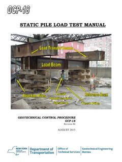
8 In9-kip15-kip20-kip25-kip30-kipLateral LoadFrom LPILE Technical ManualWQpP= soil pressureMVFrom LPILE Technical ManualList of Recs Given To Bridge Engineer Global Stability Settlement Amounts and Rates Spreads versus Deep Foundations Lateral Resistances Special Provisions/Materials Specifications Construction Considerations Water control Surface preparation Temporary Walls Vibrations Geotechnical Instrumentation needed?Doug Parmerlee Overview of Abutment Design ConceptsGeotechnical Engineering During ConstructionGeotechnical Field Monitoring pile Axial Capacity Settlement Rates and Amounts Geosynthetics: Limits/Continuity/Splicing Lightweight Fills: Limits/MaterialsPDA with Dynamic Signal MatchingStatic pile load TestsSoil Pore Pressure DissipationMEId zdx=22 Michigan s State Fossil:MastodonAncient Glacial Lake Beach on top ofGrand Portal Point, Pictured Rocks