Transcription of AC Capacitor Application Guide
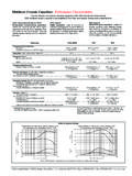
1 AC AC Capacitor Application Guide This Guide covers Cornell Dubilier s AC Capacitor types in depth and discloses the latest information on performance and appli-cation. CONTENTS PAGE Capacitor Construction 1 Characterization and Circuit Model 1 Rated Temperature 1 Rated Capacitance 2 Dissipation Factor (DF) 2 Equivalent Series Resistance (ESR) 2 RMS Current 2 Leakage Current 2 Insulation and Grounding 2 Voltage Withstand Test 2 Self-Resonant Frequency 2 Dielectric Absorption 2 Vibration Withstanding Capability 2 Safety Considerations 2 Reliability and Lifetime 2 Failure Modes 2 Early Life Failures 2 Wear-Out 2 Operating Life 2 Shelf Life 3 Mounting 3 Typical applications 3 - Motor Run 3 - Power Supply 3 - Power Factor Correction 3 TABLES Capacitor Parameter Formula 215 Expected Life vs Applied Voltage and Case Temperature 217 AC Capacitor CONSTRUCTION Cornell Dubilier s AC capacitors are constructed with biaxially oriented metallized polypropylene flm wound into a cylindrical roll.
2 End contact is formed by zinc metal spraying all of the layers on each side of the winding which assures low ESR and low inductance. Metallized polypropylene flm provides a self healing mechanism in which a dielectric breakdown clears away the metallization and isolates that area of the Capacitor within microseconds. These capacitors boast low losses where very low Dissipation Factor and ESR allow for relatively high current density. Capacitor SERIES EQUIVALENT CIRCUIT MODEL Figure 1 Rs Ls PARAMETRIC CHARACTERIZATION The table below shows useful Capacitor parameters for the series equivalent-circuit model shown schematically in Figure 1.
3 Parameter Unit Symbol Formula Approx. Capacitance farads (F) C Capacitive Reactance ohms ( ) Xc 1/(2 fC) Z Current amperes (A) I C(dV/dt), Vz/Z Dissipation Factor none DF Rs/Xc, 2 fCRs, tan( ), cot( ) PF Energy Joules (J) E CV Equivalent Series Resistance ohms ( ) Rs DF/(2 fC) Frequency hertz (Hz) f Impedance ohms ( ) Z [Rs +(Xc X) ] LXc Inductance henries (H) Ls Inductive Reactance ohms ( ) XL 2 fLs Loss Angle degrees ( ) tan-1(DF) Phase Angle degrees ( ) cot-1(DF) Power watts (W) P I Rs Power Factor none PF Rs/Z, sin( ), cos( ) DF Quality Factor none Q Xc/Rs, 1/DF, cot( ), tan( ) 1/PF Self-Resonant Frequency hertz (Hz) o 1/[2 (LC) ] Voltage volts (V) V Vc=IXc, Vz=IZ Volt-Amperes V-A VA IVz, I Z DEFINITIONS RATED TEMPERATURE The rated temperature is the range in temperature in which the capacitors will perform to their full rated service life objective.
4 Typically AC capacitors will have a rated temperature of 40 to +70 C for a motor run Application and -40 to +90 C for a power supply type Application . 1 AC RATED CAPACITANCE The rated capacitance is the nominal capacitance and it is specifed between 50Hz to 120Hz and a temperature of 25 C. The rated capacitance is also the capacitance marked on the unit. DISSIPATION FACTOR (DF) Dissipation factor is the measurement of the tangent of the loss angle (tan ) expressed as a percentage. It is also the ratio of the ESR to the capacitive reactance and is thus related to ESR by this equation: DF = 2 fC(ESR)/10,000 Where DF is a unit-less number expressed in percent, test frequency f is in Hz, capacitance C is in F and ESR is in.
5 EQUIVALENT SERIES RESISTANCE (ESR) The equivalent series resistance (ESR) is a single resistance representing all of the ohmic losses of the Capacitor and connected in series with the capacitance. RMS CURRENT AC capacitors with x blade style terminals can handle a maximum RMS current of 15 Arms, including harmonics, 60 Arms for the enclosed block terminals. LEAKAGE CURRENT When energized between their shorted terminals and the Capacitor case at a potential of 115 Vac 60 Hz their leakage current shall not exceed the following: Nominal Capacitance Leakage Current 0 - 14 F 60 A - 20 F 70 A - 35 F 100 A - 80 F 150 A INSULATION AND GROUNDING AC capacitors are manufactured to minimize electrical leakage from terminal to terminal and terminal to case.
6 Due to the non ideal nature of all insulating materials a maximum allowable leakage current to the case as well as between terminals has been established. Grounding of the metal case is recommended. VOLTAGE WITHSTAND TESTS AC capacitors are designed and 100% tested to withstand a potential diference equal to X rated AC voltage between terminals and 2 X rated AC voltage plus 1,000 volts for one second between terminals and case. SELF RESONANT FREQUENCY The self-resonant frequency is the frequency at which the capacitive reactance (1/2 fC) equals the inductive reactance (2 fL). At this point, where its impedance approaches zero, the Capacitor can be considered to be purely resistive.
7 At frequencies above self resonance, the Capacitor is inductive. DIELECTRIC ABSORPTION Is a property of an imperfect dielectric material that allows the Capacitor utilizing this material to absorb and accumulate a certain amount of energy even after being completely discharged. These charges will accumulate in the dielectric body and not on the Capacitor plates (electrodes). Dielectric absorption can be approximated by the ratio of the voltage before discharge to the self recharged (absorbed) voltage level. VIBRATION WITHSTANDING CAPABILITY AC capacitors are manufactured to withstand a test outlined in the EIA 186-7E STD of (10 to 55Hz per plane) test method III with modifcation to the duration time which is reduced to 30 minutes from of 120 minutes equating to 5G.
8 SAFETY CONSIDERATIONS The Capacitor s safety pressure interrupter is designed to disconnect the Capacitor element as the cover expands upward due to gas pressure build up. Catastrophic failure may result if movement of the cover and or terminals are restricted. Rigid bus bars are not recommended as they may restrict movement of the cover or terminals. Customers are advised to provide at least clearance above the cover to allow for its expansion. RELIABILITY AND LIFETIME AC capacitors are rated for a full service life of 60,000 h with an estimated 94% survival rate when operated at full rated voltage, 60 Hz and rated ambient temperature. FAILURE MODES AC capacitors feature an internal mechanical pressure Interrupter that disconnects the Capacitor winding from the voltage source in the event of failure.
9 Failure occurs in open circuit mode. In either event the Capacitor will remain in an open circuit mode. EARLY LIFE FAILURES Early-life failures are mostly associated with short-circuit failures from imperfections in the dielectric system. Incidences can be reduced with extended aging or burn-in. WEAR-OUT Wear-out failures are mostly open-circuit failures where the integral Pressure Interrupter mechanism has been activated due to material fatigue (wear-out). OPERATING LIFE Onset of wear-out is determined mainly by the Capacitor s rated voltage and temperature and is relative to the actual applied 2 AC Lrated is the rated operating life in h, (60,000 h) Loperation is the expected operating life in h, Trated is the rated operating temperature in C, Tapplied is the actual temperature applied to the Capacitor in C, Vrated is the Capacitor s rated voltage in Vrms, Vapplied is the actual voltage applied to the Capacitor in Vrms.
10 In addition the chart below can be utilized to estimate service life when AC capacitors are to operate at specifc conditions outside of the rated specifed conditions. voltage (both at the fundamental frequency and any harmonic content) and ambient temperature. Operating life can be expressed as (Tr - To)/10) L = L x 2 orx V r Where V oSHELF LIFE AC capacitors are expected to perform for their full service life objective after being exposed to a maximum shelf life of 10+ years when stored in a controlled environment. MOUNTING AC capacitors are manufactured in round and oval metal cases which can be fastened and mounted by a variety of methods.