Transcription of AC/VCR - Loren Cook Company
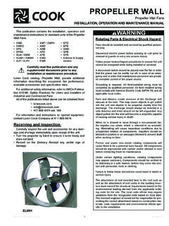
1 AC/VCR . Centrifugal Roof and Wall Exhausters INSTALLATION, OPERATION AND MAINTENANCE MANUAL. This publication contains the installation, operation and maintenance instructions for standard units of the AC &. VCR: Centrifugal Roof and Wall Exhausters. Rotating Parts & Electrical Shock Hazard: Carefully read this publication and any supplemental documents prior to any Fans should be installed and serviced by qualified person- nel only. installation or maintenance procedure. Loren Cook catalogs, AC and VCR, provide additional Disconnect electric power before working on unit (prior to removal of guards or entry into access doors). information describing the equipment, fan performance, available accessories and specification data. Follow proper lockout/tagout procedures to ensure the unit For additional safety information, refer to AMCA Publica- cannot be energized while being installed or serviced.
2 Tion 410-96, safety Practices for Users and Installers of In- dustrial and commercial Fans. A disconnect switch should be placed near the fan in or- All of the publications listed above can be obtained from: der that the power can be swiftly cut off, in case of an emergency and in order that maintenance personnel are provided complete control of the power source. 417-869-6474 ext. 166 Grounding is required. All field-installed wiring must be completed by qualified personnel. All field installed wiring For information and instructions on special equipment, must comply with National Electric Code (NFPA 70) and all contact Loren Cook Company at 417-869-6474. applicable local codes. Receiving and Inspection Fans and blowers create pressure at the discharge and vacuum at the inlet. This may cause objects to get pulled Carefully inspect the fan and accessories for any dam- into the unit and objects to be propelled rapidly from the age and shortage immediately upon receipt of fan.
3 Discharge. The discharge should always be directed in a Turn the wheel by hand to ensure it turns freely and does safe direction and inlets should not be left unguarded. Any not bind object pulled into the inlet will become a projectile capable Inspect dampers (if included) for free operation of all of causing serious injury or death. moving parts When air is allowed to move through a non-powered fan, Record on the Delivery Receipt any visible sign of the impeller can rotate, which is referred to as windmill- damage ing. Windmilling will cause hazardous conditions due to unexpected rotation of components. Impellers should be Handling blocked in position or air passages blocked to prevent draft Lift the fan by the lifting lugs provided when working on fans. under top cap. NOTICE! Never lift by Friction and power loss inside rotating components will the shaft, motor or housing.
4 Cause them to be a potential burn hazard. All components should be approached with caution and/or allowed to cool Storage before contacting them for maintenance. If the fan is stored for any length of Lifting Lugs time prior to installation, store it in its original shipping Under certain lighting conditions, rotating components crate and protect it from dust, debris and the weather. may appear stationary. Components should be verified to be stationary in a safe manner, before they come into con- Installation tact with personnel, tools or clothing. If the fan was delivered with the motor unmounted, see Failure to follow these instructions could result in death or the maintenance sections for belt and pulley installation. serious injury. The attachment of roof mounted fans to the roof curb as well as the attachment of roof curbs to the building struc- ture must exceed the structural requirements based on the environmental loading derived from the applicable build- ing code for the site.
5 The local code official may require variations from the recognized code based on local data. The licensed engineer of record will be responsible for prescribing the correct attachment based on construction materials, code requirements and environmental effects ACE ACRU ACW specific to the installation. ACSC. VCR. AC/VCR IO&M 1 B51003-002. Wall Exhausters Downblast If the fan is a wall mount unit and a grease terminator or grease trough was not purchased, a 1-1/16 inch diame- cap ter drain hole should be inserted on the bottom side of the Top unit for drainage. Wires If your fan is a wall exhauster with a round base, a mounting template is shipped with the fan. Use the tem- plate to locate the necessary lag screws or anchor bolts on the wall. The fan can then be lifted and attached easi- Motor ly.
6 Secure with lag screws, anchor bolts, or other suitable fasteners. Baffle Wheel VCR Installation 1. Ensure the fan discharge is a minimum 40 inches above Conduit the roof the roof surface and a minimum of 10 foot from any Inlet building air intake in order to comply with NFPA 96. 2. Minimum exhaust velocity in the duct should be 1500 FPM. in accordance with NFPA 96. 3. If the fan is installed on a surface that is not level, install Upblast the fan in a position that places the drain tube at the low- est position. cap Top 4. Secure the fan to the roof curb at all four corners using a minimum of four anchor bolts, lag screws or other suitable Wires fastener. Vent Tube Conduit for junction Damper Installation (used for grease). If your fan is supplied with dampers, follow the direc- Motor tions below.
7 1. Place the damper inside the curb or inside the duct work. Ensure the damper will open freely for the correct direction Baffle Wheel of the airflow. 2. Secure to curb at the damper shelf. 3. Drill hole in the curb shelf for conduit needed for motor wiring. Conduit Inlet 4. Operate the dampers manually to ensure the blades move Conduit for junction freely. (used for Smoke 5. Install fan over curb while aligning the conduit location with Control). the conduit hole in the curb. For further information refer to the National Elec- trical Code and the wiring diagram provided on Smoke Control: the motor. Use of any backdraft dampers is not permitted. Fire damp- Leave enough slack in the wiring to allow for motor ers and/or smoke dampers may be required in a smoke movement when adjusting belt tension.
8 Some fractional control system. These dampers must meet the require- motors have to be removed in order to make the connec- ments determined by the local code authority. tion with the terminal box at the end of the motor. NOTICE! Follow the wiring diagram in the discon- Wiring nect switch and the wiring diagram provided with the ACRU Upblast units have two wiring conduits. The hor- motor. Correctly label the circuit on the main power izontal conduit is directly above the vertical conduit. ACE box and always identify a closed switch to promote downblast units have a single vertical conduit. safety ( , red tape over a closed switch). The motor's wiring box is the approved field wiring com- 1. Remove the top cap which covers the motor assembly partment of the unit for ACE, ACRU and ACW units.
9 The by unlatching the snap clips. motor's wiring box may be on the side of the motor, the 2. For internal wiring, run the electrical wire and conduit shaft end of the motor or the opposite shaft end of the mo- through the opening drilled in the damper shelf (refer tor. If an additional field wiring compartment is added, then to Damper Installation), then through the wiring con- an approved metal box with cover must be secured to the duit in the ventilator base to the motor compartment. unit with two screws in order that the box does not rotate. For external wiring, run the wires through the horizon- All wiring must be protected from abrasion where they en- tal conduit on upblast units, or under top cap in down- ter and exit. The ground wire must be secured under the blast units. green ground screw within the field wiring compartment.
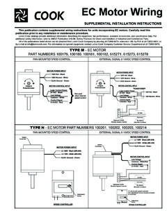
10 3. Pull the wires through and complete the wiring. See motor wiring diagram, NEC and local code for addi- tional details. Use the following diagrams to wire the motor except for For VCR and ACSC units a separate NEMA 3 field EC and EC/PM wiring diagrams; see additional supplement. wiring compartment is provided on the exterior of the unit. AC/VCR IO&M 2 B51003-002. Wiring Diagrams Typical Damper Motor Schematic Single Speed, Single Phase Motor Fan L3. Ground A L2. Motor L1. L1. T-1. Line T-4. L2 Transformer** Transformer**. Ground B. When ground is required, attach to ground A or B with No. 6. thread forming screw. To reverse, interchange T-1 and T-4. Damper Second 2 Speed, 2 Winding, Single Phase Motor Damper Motor* Motor Ground A. High Speed For 3-Phase, damper motor voltage should be the same between T-1 L1 and L2.