Transcription of AC Watt Meter Project - Webpage of the family Rosseel
1 1 AC watt Meter Project 2014-09-08 Danger (Only for the non mains isolated versions) Important Warning! Safety issue: All electrical parts of the Meter are connected to the live mains supply. Do NOT touch any of those parts when the watt Meter is connected to the mains outlet. Danger for Electrocution! The wattmeter itself should be put in a well isolated encasement that will not allow any touching of any part of it. Mind the LCD metal parts and switches/pushbuttons! Do NOT connect the circuit to a PC (via Rs232 or USB ) because it will lead to a short circuit. Do not use an external mains adapter to feed the Wattmeter ( a mains adapter for a USB device or mobile telephone). There is a danger of touching live mains supply when touching the adapter or adapter cable. The only safe choices to feed the wattmeter are - batteries inside the (isolated) wattmeter housing (mind the on/off switch!!). - a separate power supply (trafo, rectifier, stabilizer) fed from the mains supply, also inside the wattmeter housing (mind the on/off switch!)
2 !). See also section for details. Table of Contents 1 Introduction .. 2 2 Principle of working .. 3 The voltage measuring circuit .. 3 The current measuring circuit .. 4 The sampling .. 4 The calculations .. 5 Scaling .. 5 Calculating Voltage and Current RMS values (Vrms and Arms) .. 5 Calculation of the Apparent Power, Real Power (Watts) and PowerFactor .. 6 2 3 Appendixes .. 6 Electrical units .. 6 Considerations .. 7 Safety (push button, trafo, batteries, ) .. 7 Power supply .. 7 LCD .. 7 8 Stability .. 8 Circuit Diagram .. 9 Adaptations to other circumstances .. 9 To another mains voltage .. 9 To another maximum current .. 10 Adding Mains Isolation .. 13 Adaptations for other measuring frequencies .. 14 Adaptations for other PICs or clock speeds.. 15 1 Introduction This Meter is built with as less as components possible. It is of course a little limited in range, accuracy and stability.
3 It is made for 230V~ (rms), max ~ (rms) and 50Hz, but is rather easily adaptable to other voltages, currents and frequencies. It can handle both sinusoidal and non sinusoidal voltages and currents, both with and without DC component. It measures: the Rms voltage (unit: Volt) the Rms current (unit: Amp re) the apparent power consumption (unit: VoltAmp re: VA, the product of both the rms Voltage and the Rms current). This value is also called Complex power . the real power consumption (unit: watt ) (= the one that you are going to pay for) the power factor (no unit, ratio of real power to the apparent power), is the same as cos (cos phi) for sinusoidal voltages and currents. All values are shown on an LCD, except for the Apparent (Complex) power. The Meter measures once per second. Additionally there is one push button to set the zero point for the AD convertors. The values of these zero points are stored in Eeprom and recalled after startup of the PIC.
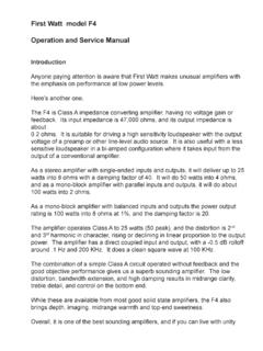
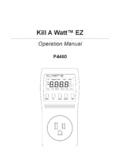
4 3 2 Principle of working The Project is built around an P18F2550, but any pic with an ADC will do, provided it is fast enough and has enough rom/ram (8988 bytes1 / 548 bytes). The voltage measuring circuit The mains voltage (the one across the load) is divided by a factor 230 and shifted to a DC level of V. This voltage is then fed to an ADC input (AN0) of the PIC. The level shifting enables to measure positive and negative voltages. The circuit: Keep in mind that GND is no earth potential, it is only the GND for the PIC. It carries live mains voltages! See also section to change the wattmeter to another nominal mains voltage. 1 when using Janni s replacement libraries: 5784 bytes romcode. 4 The current measuring circuit The current through the load is translated to a voltage of 1V per A via as series resistor, this means that the series resistor has a value of 1 Ohm.
5 The level shifter to DC is also there, but it also halves the sensitivity of the circuit, it becomes per A, or 2A per Volt. The circuit: Keep in mind that GND is no earth potential, it is only the GND for the PIC. It carries live mains voltages! See also section to change the nominal current of the wattmeter. The sampling Of both analog inputs (AN0 for the voltage, AN1 for the current) 100 samples are taken, one every 400 microseconds. This means a total measuring time of 40 milliseconds, which is 2 full 50Hz cycles. 2 full AC cycles is the minimum suitable for this type of measurement. In this Project voltage and current sampling can not be taken simultaneously (as it should be), they are taken in sequence. This gives a little phase error between voltage and current measurement, which be can normally be neglected . 5 These raw measurements are stored in 2 word arrays for further processing. It is very important that the whole measuring cycle (here 100 samples) takes exactly a full number of AC periods.
6 The sampling code becomes: for I := 0 to (NR_OF_MEASUREMENTS2 - 1) do begin VRaw[I] := ADC_Read(0); // takes 37 us3 ARaw[I] := ADC_Read(1); // takes 37 us delay_us(326); // makes a total of 400 us (= 40 ms total for all measurements = 2 full 50Hz cycles) end; The calculations Scaling First the samples taken are translated (scaled) to actual volts and amperes, which are no words but reals . This means the offset has to be subtracted (value = nominal 511, the middle of the ADC range), and multiplied with a constant value to get the correct Volt and Current values out of the samples. For the voltage the multiplication factor is , for the current the factor is 2/R4 (in our case: the value is ). Furthermore both have to be multiplied with the voltage per ADC step, in both cases the value 5/1024 (5V, 1024 steps). So, the multiplier formulas here become: const Vdd = ; // the PIC supply voltage is 5V nominal VMultiplier = Vdd / * ; AMultiplier = Vdd / * ; // I nominal = 2/R4 = The final formulas to become Volts and Amperes are: VReal := VMultiplier * real(integer(VRaw[I] - VOffset)); AReal := AMultiplier * real(integer(ARaw[I] - AOffset)); Now we have the translated ADC values into real Volt and Amp re values.
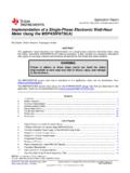
7 Calculating Voltage and Current RMS values (Vrms and Arms) For both holds: The RMS value (or the effective value) is the square Root of the Mean of all samples Squared. This means: the square of all scaled samples is calculated their average (mean) is calculated from those squared samples 2 NR_OF_MEASUREMENTS is 100 here 3 measured value in a PIC18F2550 running at 48 Mhz 4 In the actual Project this value (which can deviate from ) is stored in eeprom and read back in at startup. Pushing S1 (while no AC voltage or current is applied) stores the V and A Offset values in eeprom. 6 the square root is taken from that average. In formula form: wherein x1, x2, .. xn are the scaled sample values, n is the number of samples and xrms is the RMS value calculated from those samples. x stands for voltage or current (amperes). Calculation of the Apparent Power, Real Power (Watts) and PowerFactor The apparent power (Volt Amp res, VA) This is the easy one: the product of the RMS voltage and the RMS current.
8 In formula form: S(in VA) = Vrms * Arms The real power (watts, W) The real power is The average (mean) of all products of V and A scaled samples. In formula form: P (in W) = ( ) wherein v1, v2, .., vn are the scaled voltage samples, a1, a2,..,an are the scaled current samples and n is the number of samples. The PowerFactor The PowerFactor is The Real Power divided by the Apparent Power. In formula form: PF = P(in W) / S(in VA) 3 Appendixes Electrical units Electrical entity Unit Unit Abbrev Symbol Tension or voltage Volt V UorV current Amp re A I Real (active power) watt W P Apparent Power5 Volt-Amp re VA S Resistance Ohm R Power Factor - - PF6 or cos 7 5 or Complex power 6 F on the LCD 7 the cosine of phi , the angle between voltage and current. This notation can only be used with sinusoidal voltages and currents. 7 Considerations Safety (push button, trafo, batteries, ) Only for the non mains isolated versions Important Warning!
9 Safety issue: All electrical parts of the Meter are connected to the live mains supply. Do NOT touch any of those parts when the power Meter is connected to the mains outlet. Danger for Electrocution! The wattmeter itself should be put in a well isolated encasement that will not allow any touching of any part of it. Mind the LCD metal rim and switches/pushbuttons! Mind the fact that also the LCD is connected to the live mains power. Make sure the metal rim around the LCD can not be touched!!! The LCD should be inside the (well isolated, transparent) encasement of the wattmeter. Do NOT connect the circuit to a PC (via Rs232 or USB ) because it will lead to a short circuit. Do not use an external mains adapter to feed the Wattmeter ( a mains adapter for a USB device or mobile telephone). There is a danger of touching live mains supply when touching the adapter or adapter cable. The only safe choices to feed the non isolated wattmeter are - batteries inside the (isolated) wattmeter housing (mind the on/off switch!)
10 !) - a separate power supply (trafo, rectifier, stabilizer) fed from the mains supply, also inside the wattmeter housing (mind the on/off switch!!). - a capacitive bleeder from the mains power supply. All above should be built inside the (well isolated) encasement of the wattmeter, because all of it will be connected to live mains. For all versions: Make also sure that R1 in the circuit diagram can withstand 400 Vtop, and that R4 can dissipate 5 watt without any problems. Do not use the power Meter in the configuration described above with currents more than rms. Power supply The power supply is not drawn in the schematic diagram. It can be a battery, a transformer with rectifier and buffer capacitor or even an (capacitive) bleeder from the mains, all followed by a 5V stabilizer. See also the safety part, section LCD Also the LCD connections are not drawn in the circuit diagram. In the code PortB is used to drive the LCD.