Transcription of ACPPA TECHNICAL SERIES
1 11 ACPPATECHNICAL SERIESACPPA TECHNICAL SERIES | ISSUE 11 FLOW FRICTION CHARACTERISTICS OF CONCRETE PRESSURE PIPEThis paper presents formulas to assist in hydraulic design of concrete pressure pipe. There are many formulas to calculate the head loss from flow friction in a pipeline; however, there are three formulas that are typically used in the industry. These three are presented in this paper. Also, the method used to determine minor and total head losses are pressure pipe lining is produced either by centrifugal casting or, as for the lining in this picture, by vertical wet-casting against a smooth steel most frequently used formulas by the waterworks industry in establishing the capacity of pipelines are the Hazen-Williams formula, the Darcy-Weisbach formula and the Manning formula. Any of these formulas are acceptable in the industry.
2 The user of this information is cautioned not to expect identical answers to a problem from the three formulas. The proper formula to be used in a given condition remains a matter of engineering FLOW COEFFICIENTSIt is important to note that new pipe of any material or lining will almost always have better flow coefficients than pipe in service for a period of time. Even in pipelines conveying disinfected water, biofilms are common on the pipe lining surface. In raw water lines, biofilms can include fibrous growths that significantly disrupt smooth flow, regardless of the pipe lining material. Chemical deposits can occur from some waters. Water pipe linings may also be corroded or roughened by scouring. The coefficients presented herein are based upon data determined from pipelines in service for a period of time, and for most applications may be used to approximate the anticipated performance of new installations.
3 Even so, each installation must be evaluated for circumstances that may degrade flow over time. Pig insertion stations, chemical treatment facilities, specific linings, or other pipeline appurtenances may be justified to assure ACPPA TECHNICAL SERIES | ISSUE 11that continuing flow degradation does not result in unnecessarily excessive pumping HAZEN-WILLIAMS FORMULAP robably the most popular flow formula in current use in waterworks engineering is the Hazen-Williams formula. The advantage of this equation is that the coefficient C is not a function of the Reynolds number. Its disadvantage is that it is valid only for water and does not account for temperature or viscosity variations. This formula was developed and published in the early 1900 s as: V = : V = velocity, ft/sec Ch = Hazen-Williams roughness coefficient r = hydraulic radius of pipe, ft s = slope of hydraulic grade line, ft/ft calculated as hL/L, where hL equals head loss in feet occurring in a pipe of length L in ft.
4 For circular conduit flowing full, the head loss hL may be calculated from:hL = ( L)/( )Where: hL = frictional head loss in pipe length L, ft Q = discharge, ft3/sec L = length of pipe, ft d = inside diameter of pipe, ftTests have shown that the value of the Hazen-Williams coefficient Ch is dependent not only on the surface roughness of the pipe interior but also on the diameter of the pipe. Flow measurements indicate that for pipe with smooth interior linings in good condition, the average value of Ch = + , for design purposes the following conservative values are suggested: Diameter, in. Ch Value 16 to 48 140 54 to 108 145 114 and larger 150 THE DARCY-WEISBACH FORMULAThe second formula frequently used in waterworks engineering is the Darcy-Weisbach formula. Its general form can be derived analytically for laminar flow, and it can be used for any fluid.
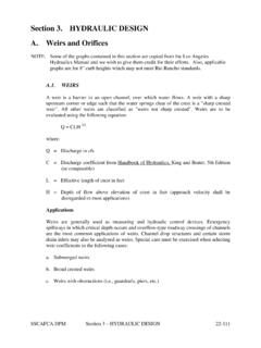
5 The formula is: hL = f L V2 / d 2gWhere: hL = Head loss, in feet of water f = Darcy friction factor L = pipeline length, ft V = velocity, ft/sec d = inside diameter of the pipe, ft g = gravitational constant, ft/sec2 Centrifugal casting packs the aggregate into the lining, resulting in a smooth pipe Darcy friction factor (f) is determined from the Moody diagram, illustrated in Figure 1. The Reynolds number (Re) and the relative roughness (e/d) must first be Reynolds number is a function of the flow in the pipe and may be calculated as: Re = d V / vWhere: Re = Reynolds number d = inside diameter of the pipe, ft V = velocity, ft/sec v = kinematic viscosity of the fluid, ft2/secThe kinematic viscosity of water at various temperatures from freezing to boiling can be obtained from any hydraulic relative roughness (e/d) of a pipe is a function of the absolute roughness (e), in feet, of the interior surface of the pipe and the pipe diameter (d), in feet.
6 Values of the absolute roughness (e) for concrete pipe range from x 10-5 to x 10-4, and the recommended design range is x 10-4 to x 10-4. Once the Reynolds number and the relative roughness are determined, the Moody diagram (figure 1) can be used to determine values of the Darcy friction factor (f), which may then be used to solve the Darcy-Weisbach an analytical solution for the Darcy friction factor (f) is required, it may be obtained by interaction from the Colebrook-White equation: 1/ f = -2 log10 [( ) + ( f)]Where: f = Darcy friction factor e = absolute roughness, ft d = inside diameter of the pipe, ft Re = Reynolds numberTHE MANNING FORMULAThe third formula frequently used in the water industry is the Manning formula. This formula is more commonly used to establish the flow in partially filled gravity lines; however it can be used for fully developed flow in conduits.
7 The formula for pressure flow in round conduits is: V = ( ) (hL/L) : V = velocity, ft/sec d = inside diameter of the pipe, ft hL = head loss, in feet, in a length L, ft nM = Manning roughness coefficientThe recommended Manning roughness coefficient value nM for concrete pressure pipe should be approximately when the velocity is 3 ft/s and when the velocity is 5 ft/s. MINOR LOSSESM inor losses in pipelines are caused by turbulence resulting from changes in flow geometry. Minor losses, which are generally expressed as a function of the velocity head, will occur at entrances, outlets, contractions, enlargements, bends, and other fittings. In long pipelines, the minor losses are usually small compared to losses from pipe friction and may be neglected. In shorter lines or plant piping, the sum of these minor losses may become significant.
8 The formula for calculating minor losses is: hL = CLV2/(2g)Where: hL = head loss, ft CL = a dimensionless coefficient V = velocity, ft/sec g = gravitational constant, ft/sec2 Figure 2 presents values of CL for common flow configurations. CONCRETE PRESSURE PIPEThe Moody diagram for friction in pipeFigure 3-3 Figure 3-3 The Moody diagram for friction in pipe18 CONCRETE PRESSURE PIPEC opyright (C) 1999 American Water Works Association All Rights ReservedFigure 1. The Moody diagram for friction in pipe. Reprinted from AWWA Manual M9, 3rd edition by permission. Copyright 2008 the American Water Works CONCRETE PRESSURE PIPEA pproximate loss coefficients for commonly encountered flow configurationsFigure 3-4 Figure 3-4 Approximate loss coefficients for commonly encountered flow configurations22 CONCRETE PRESSURE PIPEC opyright (C) 1999 American Water Works Association All Rights ReservedFigure 2.
9 Approximate loss coefficients for commonly encountered flow configurations. Reprinted from AWWA Manual M9, 3rd edition by permission. Copyright 2008 the American Water Works University DriveSuite 110 Fairfax, VA 22030-2513 T TECHNICAL SERIES | ISSUE 11 For more information on flow friction characteristics, speak with your Concrete Pressure Pipe supplier, or contact the American Concrete Pressure Pipe Association at or LENGTH METHODEach minor head loss in a piping system can be expressed in terms of an equivalent length of pipe Le. This equivalent length of pipe is the number of feet of straight pipe that would have friction head loss equal to the minor losses created by the fitting. The list below shows the equivalent length formulas that correspond to the flow formulas presented Formula Equivalent Length FormulaHazen-Williams Le= ( )/2gDarcy-Weisbach Le = CL (d/f)Manning Le = ( )/2g(nM)2 Where: Le = length of pipe that would have a frictional lead loss equal to the minor loss created by fitting, ft CL =loss coefficient V = velocity, ft/sec d = inside diameter of the pipe, ft Ch = Hazen-Williams roughness coefficient g = gravitational constant, ft/sec2 f = Darcy friction factor, nM = Manning roughness coefficientHEAD LOSSThe total head loss in a pipeline is the sum of minor losses due to changes in flow geometry added to the head loss created due to the friction caused by flow through the pipe.
10 The head loss for the pipeline can be used to calculate the pumping costs which will be incurred for various diameters of pipe. The pumping costs can be compared to the initial costs for the various diameters of pipe so that the most cost-effective size of pipe can be