Transcription of Active Filter Design - CK Electronic
1 Active Filter Designby Carsten KristiansenNapier UniversityNovember 2004 Title page Author:Carsten Kristiansen. Napier No: 04007712. assignment partner:Benjamin Grydehoej. assignment title: Active Filter Design . Education: Electronic and Computer Engineering. Module:Engineering Applications SE32101. Place of education:Napier University Edinburgh10 Colinton RoadEdinburgh EH10 5DT assignment advisor:Dr. MY Sharif. assignment period:1. November 2004 - 26. November AbstractThis report describes how an Active low pass Filter is designed, simulated and tested. The Filter ishere constructed from some given specifications, where one of them is that the Filter need to have aButterworth response.
2 The procedure we in this group have chosen to solve the assignment , is todesign the Filter with two different methods, one with a Sallen and Key architecture and the other iswith the Multiple-Feedback (MFB) architecture. Contents1. Butterworth assignment Filter Sallen and Low-pass Multiple Feedback (MFB).. Low-pass Test and Test Gain Phase Pole point Software Appendix 1 Calculations from Appendix 2 Measurement Appendix 3 Oscilloscope Filter DesignCarsten Kristiansen Napier No.: 040077122. IntroductionToday noise reduction is a very hot topic. In this case it is electrical noise in a digitalcommunication system, that needs to be reduced.
3 The purpose of reducing (band limit analoguesignal) the noise is cause its not wanted in the following sampling and encoding process. Like in thegiven assignment , it is very common to insert some kind of Filter in DSP applications, where a falseinput signal can be critical to the outcome on the before Op-Amps were available electrical filters have been used. That was when only passivecomponents such as resistors and capacitors could be used for the filters. Today the Op-Amps arelow-cost and very reliable Active devices, which is the reason for mainly using Active filters today. There are various types of Active filters where some of them are named Chebyshev, Bessel andButterworth.
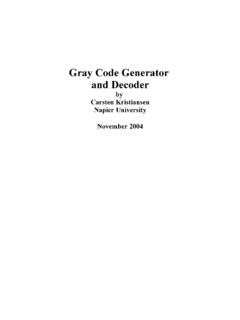
4 The Design process of the filters can consist of different types of architectures, wherethe two most common are named Sallen and Key, and Multiple Feedback (MFB) architecture In thisassignment the Filter is an Active low-pass Filter with a Butterworth response. To satisfy our owncuriosity and examine the differences, we will Design the Butterworth Filter with both of the abovedescribed Butterworth filtersThe figure 1 below shows the actual responses for three different types of filters the Bessel,Chebyshev and the Butterworth Filter . The Butterworth response is the one that is we are going toconcentrate about in this 1: Actual Filter responsesThe characteristics for the butterworth Filter response are: Maximal flat magnitude response Filter .
5 Optimised for gain flatness in the passband. -3dB at the cut-off frequency. -20dB per decade per order above the cut-off frequency. Transient response to a pulsed input shows moderate overshoot and UniversityCarsten Kristiansen Napier No.: 04007712 Active Filter DesignButterworth polynomials:Unlike other polynomials the Butterworth polynomials requires the least amount of work, becausethe frequency scaling scaling factor are always equal to one. The transfer function for the secondorder low-pass Butterworth Filter are shown ffc 2 1,414 jffc 1 Where:K = the gain = the frequency = the cut-off normalized Butterworth polynomials for the first and second order Filter are 1,414 s 1 Where:s = j To make it easier to Design Active filters there are made some Filter coefficient tables for each typeof responses.
6 Later in the Multiple Feedback architecture the table with values for the Butterworthresponse are shown and used in the University7 Active Filter DesignCarsten Kristiansen Napier No.: 040077123. assignment specificationsIn a digital communication system an anti-aliasing low-pass Active Filter is required to band the limitof the analogue signal prior to sampling and encoding process. The Filter must satisfy the response= frequency = 3, frequency = attenuation gain= visual indication of the magnitude response of the Filter is shown in the figure 2 below: The Filter is to be designed and simulated, using TINA software development package, andinvestigate the performance of the Filter .
7 The simulation results must include a plot of the magnituderesponse of the Filter . Construct the Filter on a breadboard and investigate its performance. Plot themagnitude response of the Filter on log UniversityFig. 2: Magnitude responseCarsten Kristiansen Napier No.: 04007712 Active Filter Design4. Filter orderWith the specifications for the Butterworth Filter , it is possible to calculate the Filter order. Theresult can then be used to show how many components are needed in the Design of the Active are made with the formulas from the Filter handout. Figure 3 shows the Filter response, where the S2, cand 2 from the specifications are needed to calculatethe Filter response.
8 The 20 log 2 explains the passbandgain of main formula to calculate the Filter order:n log 1s22 1 2 log 2 c The known values are: c = 3,4kHz. 2 = 6kHz. Asb = is found:20 log S2 = 10dB S2=log 1020 1 S2=316,2mThe Filter order is calculated:n log 1s22 1 2 log 2 c =log 1316,2m2 1 2 log 60003400 =1,934 ~ n=2 The Filter order of 2 means that the Butterworth Filter now can be designed using one OP-amp forthe Sallen-Key and the MFB architectures. When the Filter order is 2, the number of resistors andcapacitors that is needed for the Filter function are also 2 of University9 Fig. 3: Filter ResponseActive Filter DesignCarsten Kristiansen Napier No.
9 : 040077125. Sallen and KeyThe Sallen and Key architecture is the easiest way to Design an Active Filter . It is the Design that usesthe least number of components, and the equations are relatively straight forward. It has beendiscussed, analysed and reviewed in great depth on the web and in text books. The Sallen and Key isvery often a preferred Design compared to the MFB architecture because it does not invert thesignal. Another advantage of using a Sallen and Key architecture, is that it is not sensitive tocomponent variation at unity gain. A disadvantage is the high frequency response of the Filter , islimited by the frequency response of the amplifier.
10 Low-pass architectureThe simplest Design of the Sallen and Key filteras a two-pole, low-pass Filter is shown in figure4 using TINA. Look aside from the componentvalues, which will be calculated to the correctvalues shortly. From TINA the general idealtransfer function for this circuit can be derived(shown below). With this transfer function it ispossible to calculate the values of the passivecomponents. Simplified formulas derived fromthe transfer function, will for that purpose beused. -The transfer functions denominator willalso be used later on to calculate the poles ofthe Filter . Low-pass Sallen and Key ideal transfer function: s = R3 R4 R3 C1 R4 R1 C2 R3 R2 C2 R3 R1 s C2 C1 R3 R1 R2 CalculationsChosen values: C1, C2 = 2,2nF.