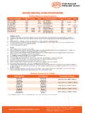
Transcription of Actuator sizing calculation for Gate & Globe Valves
1 Actuator sizing calculation for gate & Globe Valves GSL- Actuator - sizing - calculation R1 - AS Information requiredExamples1 Bore diameter at seat (use actual diameter if known)12 inch3 inch3 inch2 Differential pressure, using 30psi minimum, and line psi if higher200 psi2250 psi2250 psi3 Type of valve and serviceWedge gate , oil Globe , steamGlobe, steam4 Stem diameter and lead of screw thread (pitch x number of starts)1 x 1/3 rising stem1 x rising rotating1 x rising stem5 Travel time/speed in inches per minute (if critical)About 1 minuteMethod Having obtained the above information proceed as followsAObtain bore area (full bore assumed) (1)113 sq sq sq inBDifferential psi200 psi2250 psi2250 psiCObtain valve factor Table A x B x C to obtain seating thrust For rising stem Valves : 7950 lbfYes18200 lbfNo18200 lbfYesEAdd packing friction thrust = 2000 x stem diameter (2)For gate Valves :3500 lbfYes----No3000 lbfNoFAdd piston effect = x diam.
2 Of stem^2 x diff. Pressure (For Globe Valves , the stem area is included with the disc area, so piston effect can be ignored)481 lbf--------GD+ E+F gives total thrust11931 lbf18200 lbf21200 lbfHObtain Stem Factor K Table x H gives torqueFor rotating stem Valves :167 lbf-ftNo218 lbf-ftYes254 lbf-ftNoKAdd gland friction torque = (1000 x stem diameter^2) 12 (2)----188 lbf-ft----LJ+K gives total thrust (rotating stem)406 lbf-ftM Actuator RPM = Speed in inches per min Lead of stem12 1/3= 36 RPM Notes(1) API-600 and API-603 gate Valves must have full ports according to Annex A form ASME Valves conforming to API-602 have reduced ports indicated in this standard. Other Valves may differ according to manufacturing standard or published CV factor. Consult plant for an specific valve port diameter.(2) Factors based on Flexible Graphite Packing. For PTFE Packing, the results can be divided by 2.(3) Valve factors are based on metallic seats, when valve is new.
3 If you foresee seats oxidation or aging during the service, multiply this factors by to depending the severity of seats oxidation or aging. Stroking the valve frequently, maintain the seats cleaner and the thrust and torque lower.(4) For inside screw threads multiply factors by for exposed sluice gates (penstocks) multiply factors by and insure that thrust estimate is a minimum of three times the weight of the gate . This factors assume a proper lubrication on stem threads, if a poor maintenance is predicted multiply this factors by to Depending on the specified speed, the stems can have single, double or triple start. Consult plant for actual stem diameter, pitch and lead. Table 1 Valve Factors (3)Valve typeLiquids Below 750 FLiquids Above 750 FGases/Steam below 1000 FGases/Steam above or close 1000 FParallel slide and Flexible or double wedge above 2 below 2 LeadStem Dia In Ins3/4 1 1 1 1 22 2 2 33 3 3 44 4 4 55 5 66 1 1 1 2 1 2 1 2 1 2 Stem Factors (4)Factor is lbf-ft per lbf of thrust, for ACME thread, using a coefficient of friction equal to