Transcription of Acutrak 2 - Acumed
1 Acutrak 2 Headless Compression Screw SystemSurgical Technique2 Acutrak 2 Headless Compression Screw SystemSince its introduction in 1994, the Acutrak Headless Compression Screw technology has revolutionized the way surgeons treat fractures, fusions, and osteotomies. The Acutrak 2 is the next generation in fully threaded headless fixation offering larger guide wires, larger hex drivers, and a tapered end reducing drill depth sensitivity. Long term surgeon feedback has helped develop this continuously variable fully threaded headless implant with instrumentation designed to simplify the surgical Acutrak 2 family is composed of 67 unique screw size options to fit a wide variety of applications throughout the body, from 2 mm x 8 mm up to mm x 120 for Use3 Quick Reference Chart4 Surgical Techniques5 Volar Scaphoid Technique5 Dorsal Scaphoid Technique8 DIP Fusion Technique11 Jones Fracture Technique13 Calcaneal Osteotomy Technique17 Ordering Information21 Notes25 Acumed is a global leader of innovative orthopaedic and medical solutions.
2 We are dedicated to developing products, service methods, and approaches that improve patient Fracture and Calcaneal Surgical Technique Nicholas Abidi, Scaphoid, Dorsal Scaphoid, and DIP Fusion Surgical Technique Nicholas Goddard, MB, FRCS3 Acumed Acutrak 2 Headless Compression Screw System Surgical TechniqueIndications for UseAcutrak 2 Micro, Mini, Standard, , and are intended for use as fixation devices for small bones, bone fragments, and osteotomies. They are not intended for interference or soft tissue 2 may be used for fusions, fractures, or osteotomies of the clavicle, humerus, radius, ulna, ilium, femur, patella, fibula, tibia, talus, malleolus, and and WristFour Corner FusionDIP FusionPIP FusionPhalangeal FractureRadial Styloid FractureScaphoid Fracture/NonunionUlnar Styloid FractureMCP FusionMetacarpal Head FractureFoot and AnkleAnkle ArthrodesisTalonavicular FusionCalcaneal OsteotomyPIP FusionPIP FusionDIP FusionMTP FusionMTP FusionJones FractureCalcaneocuboid FusionSubtalar FusionTMT FusionTMT Fusion4 Acumed Acutrak 2 Headless Compression Screw System Surgical TechniqueAcutrak 2 Quick Reference ChartDiameterLengthsPropertiesMicroTip.
3 MmTail: mm8 mm 9 mm10 mm 11 mm12 mm 13 mm14 mm 16 mm18 mm 20 mm22 mm 24 mm26 mm 28 mm30 mm Where used to treat the indications described on page 3, it may be possible to use an Acutrak screw of similar size instead of the screws listed here Use in lieu of a mm Headed Screw mm Hex Driver .035" (.88 mm) Guide WireMiniTip: mmTail: mm16 mm 18 mm20 mm 24 mm26 mm 28 mm30 mm Where used to treat the indications described on page 3, it may be possible to use an Acutrak screw of similar size instead of the screws listed here Use in lieu of a mm Headed Screw mm Hex Driver .045" ( mm) Guide WireStandardTip: mmTail: mm16 mm 18 mm20 mm 22 mm24 mm 26 mm28 mm 30 mm 32 mm 34 mm Where used to treat the indications described on page 3, it may be possible to use an Acutrak screw of similar size instead of the screws listed here Use in lieu of a mm Headed Screw mm Hex Driver.
4 054" ( mm) Guide : mmTail: mm20 mm 22 mm24 mm 26 mm28 mm 30 mm35 mm 40 mm45 mm 50 mm Where used to treat the indications described on page 3, it may be possible to use an Acutrak screw of similar size instead of the screws listed here Use in lieu of a mm Headed Screw mm Hex Driver .062" ( mm) Guide : mmTail: mm25 mm 30 mm35 mm 40 mm 45 mm 50 mm 55 mm 60 mm Where used to treat the indications described on page 3, it may be possible to use an Acutrak screw of similar size instead of the screws listed here Use in lieu of a mm Headed Screw mm Hex Driver .062" ( mm) Guide Wire7. 5 Tip: mmTail: mm40 mm 45 mm 50 mm 55 mm 60 mm 65 mm 70 mm 75 mm80 mm 85 mm 90 mm 95 mm 100 mm 105 mm 110 mm 115 mm 120 mm Where used to treat the indications described on page 3, it may be possible to use an Acutrak screw of similar size instead of the screws listed here Use in lieu of a mm Headed Screw mm Hex Driver.
5 094" ( mm) Guide Wire5 Acumed Acutrak 2 Headless Compression Screw System Surgical Technique1 APPROACH AND NEEDLE INSERTIONThe procedure can be carried out using the volar traction approach or using a conventional volar type approach with the arm supine on a hand table. The volar traction approach facilitates reduction of a displaced fracture and permits arthroscopy to ensure accuracy of the reduction. Fluoroscopy is used entry point is then located using a 12 or 14 gauge IV needle introduced on the antero-radial aspect of the wrist just radial to and distal to the scaphoid tuberosity. This serves as a trochar for the guide wire and is a directional aid to establish a central path along the scaphoid. The needle is then insinuated into the scaphotrapezial joint, tilted into a more vertical position and the position is checked on the under image intensifier.
6 By gently levering on the trapezium this maneuver brings the distal pole of the scaphoid more radial and thus ultimately facilitates screw insertion. The entry point should be approximately 1/3 the way across the scaphoid from the tuberosity in the A/P plane and central in the lateral GUIDE WIRE INSERTIONPass the guide wire through the needle and drill it across the fracture, continually checking the direction on the image intensifier and correcting as necessary, aiming for the radial aspect of the proximal pole. It is extremely important not to bend the guide wire and any adjustments in direction should be made using the needle as a guide rather than attempting to alter the line of the guide wire Scaphoid Technique: Acutrak 2 Micro, Mini, and StandardNicholas Goddard, MB, FRCS6 Acumed Acutrak 2 Headless Compression Screw System Surgical Technique3 DETERMINE SCREW LENGTHA dvance the guide wire to stop just short of the articular surface as the wire should not breach it at this stage.
7 The position, alignment and length are checked once more. Make a simple stab incision at the entry point of the wire, and deepen this down to the distal pole of the scaphoid using a small hemostat and blunt the length of the screw either with the appropriate depth gauge or by advancing a second guide wire of the same length up the distal cortex of the scaphoid and subtracting the difference between the two. When using the volar approach, the correct screw size is 2 4 mm shorter than the measured length so as to ensure that the proximal tip of the screw is fully buried below the cartilage and the cortical ADVANCE GUIDE WIREA dvance the guide wire through the proximal pole of the scaphoid so as to exit on the dorsal aspect of the wrist.
8 This is a precautionary measure to minimize the risk of inadvertent withdrawal of the wire during the reaming process and screw insertion and to facilitate removal of the proximal portion if the wire were to break. A second de-rotation wire can then be inserted in those cases where it is felt that there is a possibility of rotational instability of the Acutrak 2 Headless Compression Screw System Surgical Technique5 DRILLR emove the 12 gauge needle and pass the Cannulated Profile Drill over the wire using either a power drill or by hand stopping 1 2 mm short of the articular surface. The long drill is recommended to mitigate the effects of varying bone density and distraction upon screw ADVANCE SELF-TAPPING SCREWThe self-tapping screw is then advanced over the guide wire and the wire removed.
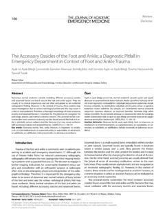
9 Compression can then be confirmed radiographically on the image Acutrak 2 Headless Compression Screw System Surgical TechniqueDorsal Scaphoid Technique: Acutrak 2 Micro, Mini, and StandardNicholas Goddard, MB, FRCS1 APPROACH AND NEEDLE INSERTIONThe entry point in the proximal pole is at the tip of the scaphoid immediately adjacent to the scapholunate ligament. This can be located either using an arthroscopy or mini open dorsal approach between the third and fourth extensor compartments. Whichever approach is employed, it is essential to ensure that the guide wire does not transfix an extensor established the entry point, introduce the appropriate guide wire aiming for the base of the thumb and check the position on the fluoroscope.
10 Aim to place the leading edge of the guide wire in the subchondral surface of the distal pole of the scaphoid. Confirm the wire placement and depth under : A 14 gauge IV Cannula is a useful aid in determining the entry point and acts as both a guide and soft tissue FRACTURE STABILIZATIONIf the fracture is unstable it may be helpful to place a second parallel guide wire using the parallel wire guides which are available for all three Acutrak 2 Screw Acutrak 2 Headless Compression Screw System Surgical Technique3 DETERMINE SCREW LENGTHM easure guide wire length using either the percutaneous screw sizer, or by placing a second wire at the entry point and subtracting the difference. The screw sizer cannot be used with the arthroscopic technique due to the limited access.