Transcription of ACWC-SD - Heating, Air Conditioning & Refrigeration
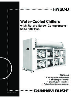
1 ! ACWC-SD Screw Type Air-Cooled Packaged Chillers installation , Operation, and Maintenance Manual DESCRIPTION TABLE OF CONTENTS Inspection & Handling Location and Mounting Wiring Chiller Piping Start-Up Maintenance Slide Valve Unloading System Low Ambient Operation Control Settings Unit Operating Limitations Sequence of Operation Safety Controls, Field Wiring, Star Delta Start Control Wiring Diagrams ACWC 40 thru 70 ACWC 90 thru 135 ACWC 145 thru 200 ACWC 215 thru 265 Power Wiring Diagrams ACWC 40 thru 70 ACWC 90 thru 135 ACWC 145 thru 200 ACWC 215 thru 265 Electrical Data Cooler Pressure Drops Unit Loading/Suspension Points Troubleshooting Guide Causes & Prevention of Freeze-Up Start-up Check List Operating Data Maintenance Form No.
2 6184 PAGE NO. 2 2 2 2 2 & 3 3 4 5 5 5 6 & 7 7 8&9 10 & 11 12 &13 14 &15 16 16 17 17 18 & 19 20 21 22 22 23 24 24 DUNHAM-BUSH USA INSPECTION & HANDLING CHILLER PIPING When unit is received, it is the responsibility of the contractor to inspect the unit for shipping damage at time of off loading and make note of damage on carrier's freight bill. ACWC units are factory mounted on (2) carbon steel angle beams. Sizes 45 thru 90 have three lifting holes per side. Sizes 110 thru 215 have four lifting holes per side and sizes 240 thru 265 have five lifting holes per side to facilitate lifting.
3 Spreader bars must be used between rigging lines to prevent damage to the unit. Rollers may be used under the skids to facilitate moving the unit a short distance. Models ACWC-40DF thru 22DC are factory mounted on two permanent angle beam, carbon steel skids. A minimum of four 2 7/8" lifting eyes are provided in the skids to allow rigging. Physical damage to the unit, after acceptance, is not the responsibility of the factory. LOCATION & MOUNTING Model ACWC Air Cooled Packaged Water Chillers are designed for outdoor application and may be mounted on roof or at ground level. Air lIow through the condenser is vertical and the unit may be located adjacent to outside of building or on roof without regard for prevailing wind direction.
4 Since these units are air cooled, the flow of air to and from the condenser coil must not be impeded. There must be no obstruction above the unit that would tend to dellect discharge air downward where it could be recirculated back to the inlet of the unit. The required overhead air space should be a minimum of eight feet. Ductwork must not be applied to the fan outlets. The unit must be installed with sufficient clearance for air entrance to the condenser coil and for servicing access. The unit should be located no closer than four feet from any wall or other obstruction. Clearance must be provided at either end of the unit to permit removal of tubes from the chiller.
5 Unit must be set on a solid and level foundation. On roof installations the unit should be mounted on support beams which span load-bearing walls to prevent excessive vibration. On ground level installations, the unit should be mounted on a substantial base that will not settle. A one-piece concrete slab with footings extended below the frost line is recommended. A space should be left between the slab and the building to prevent the transmission of sound and vibration. Vibration mounts may be used for roof-mounted units or other locations where noise might be objectionable. WIRING A unit wiring diagram showing the required power supply characteristics and all factory supplied wiring details are provided with unit.
6 Separate, field supplied, disconnects must be installed for the power and control circuits and should be within the sight of the unit. Separate 115-volt power source must be field supplied to provide power for control and heater circuits if optional control circuit transformer is not provided. All electrical connections should be periodically tightened. The chiller inlet (return) water pipe should be connected to the water connection closest to the control panel end of the unit and the outlet (supply) water pipe connected to the water connection on the opposite end of the cooler(s). A flow switch must be installed in a straight horizontal section of the chilled water piping.
7 This is to be field installed. Gauges should be installed in the piping to and from the chiller to measure the pressure drop and to insure the proper (GPM) flow rate in accordance with submittal data. A strainer should be installed in the piping on the inlet side of the chiller and vibration eliminators should be employed on both the inlet and outlet pipes. Air vents should be located at all high points in the piping system. Vents should be located to be accessible to servicing. Drain connections should be provided at all low points to permit complete drainage of chiller and piping system.
8 The chilled water piping should be insulated to reduce heat pickup and to prevent condensation. Ifthe system is for year-round operation or if it will not be drained in the winter, the chilled water piping should be protected against freezing by electric heating cable or other suitable means. Upon completion of chiller piping, start the system water pump and purge air from the system. Air purging should be done from the high points in the water circuit. Purging of the chiller barrel may be accomplished through the vent pipe located on the top of the chiller compartment Failure to purge air from the water circuit will result in inadequate water flow and may cause the unit to cutout.
9 START UP Refer to start, test, and check list included with this manual. 2 CAUTION: The discharge line valve must be open before starting the compressor. Liquid line valves must also be open for sustained operation. All compressors are solid mounted on isopads, therefore, compressor hold-down bolts must not be loosened. Loosening these bolts will cause excessive vibration of the compressor and may result in refrigerant line breakage. Prior to start-up check all compressor hold-down bolts for tightness. MAINTENANCE CONDENSER Units are equipped with direct drive fans that have inherently protected motors with permanently lubricated bearings.
10 The air inlet of the condenser coil should be kept clean through a regular maintenance program. COMPRESSOR 1. OIL LEVEL - The oil level in the compressor(s) should be checked periodically, with the compressor either running or stopped. If the oil level is below one-half (1/2) the sight glass, oil must be added. 2. RECOMMENDED OIL -- The unit 4 factory-charged with DB SR-30 Refrigeration 01. Do not add any other type of oil to this factory charge. Do not operate compressor If 011 level Is below one-half (1/2) sight glass. If the oil level is below the minimum specified above, and DB SR-30 is not on hand, you may drain the entire factory oil charge, then refill with SUNISO 4GS Refrigeration oil.