Transcription of Adjustable Fuel Gauge Tube-Type Fuel Sender
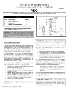
1 Adjustable fuel GaugeTube-Type fuel SenderInstallation InstructionsInstruction Sheet # 0 531 060 140 Rev. 03/09 instructions FOR THE installation OF THE Adjustable fuel Gauge AND/OR Tube-Type Sender ARE CONTAINED HEREIN. USE IS RESTRICTED TO 12-VOLT NEGATIVEGROUND ELECTRICAL SYSTEMS. LIGHT BULB, IF SUPPLIED, IS 12 and Materials Needed For installation :16 Gauge stranded, insulated wireNon-insulated " spade connectors2 " hole sawDrill and drill bit setHalf-round fileTape measure or rulerSmall tools: wrench or nut driver, utilityknife, pliers, Adjustable fuel Gauge must becalibrated before it can work prop-erly. Please read and follow all in-structions before installing !!! fuel Gauge1 fuel Socket (Push in, wedge-type) Bulb (12-volt / #158 or equivalent) Spin-Lok Clamp or Mounting Instructions1 Parts ListSender installation :Mount the Sender vertically in the deepestpart of the tank, as shown in Diagram will need to cut a 2 " ECalibrating Gauge with the Sender is necessary for accurate operationMove the pointer until itcomes to rest directly on 0 or E (whichever designatesempty on your Gauge ).
2 Note: Calibration is mandatory forgauge to work properly. Tank must beempty when calibration is performed. [text continues]CAUTION: Read these instructions thoroughlybefore making installation . Do not deviate fromassembly or wiring instructions . Alwaysdisconnect battery ground before making anyelectrical a small plastic screwdriver,turn the adjustment screwlocated in a hole on the side of thegauge housing. NOTE: Do not usea metal staticdischarge can damage the you have moved thepointer to 0 or E withthe tank empty, calibrationis complete and your gaugeis ready to After wiring Gauge / Sender , calibrate them(Diagram E). With the tank empty, use thecalibration screw to move the pointer to E. When the pointer rests on E with the tankempty, the Gauge and Sender are calibratedand ready for use, and the Gauge can the fuel Gauge :1. Run wires from the Adjustable fuel gaugelocation to:a) +12 volt power terminal(This positive power source MUSTBE SWITCHED, and should beprotected with a fuse)b) the light switch (also after thefuse in the fuse box)c) a good ground locationd) the Tube-Type fuel Wire the Adjustable fuel Gauge and Tube-Type Sender as shown in Diagram DInstall the Sender vertically in the deepest part of the tankDiagram AGauge dimensionsDiagram CAdjustable fuel Gauge Wiring to Tube-Type Sender2 QddUbiCYW^Q\ d_ C dUb]Y^Q\ _^7 QeWU 7 QeWU <YWXd C_S[Ud7b_e^T7b_e^T7b_e^T6ecU2_h<YWXdCgYd SXCgYdSXUT !
3 "f7 QeWU DUb]Y^Q\c V6eU\ CU^TUb_b<YWXd C_S[UdcVDUb]Y^Q\cBUQb _V 7 QeWUc Cut a 2 " sure tomount thesender vertically inthe deepest part ofthe senderinto tank,notchfirst Remove tape thatcovers float set asshipped Hook up the Sender wires to thegauge (Diagram C) and calibrate(Diagram E).Diagram BProper mounting with VDO s Spin-Lok Clamp or mounting bracketMounting Nut directiondepends on panel widthA: 0 .4" (0 10 mm)B: .4" .8" (10 20 mm)At this point, the installation , wiring and cali-bration of your new VDO Gauge and/orSender is complete. Turn on the ignitionand lights and check to see that the instru-ment and light work properly. If they don t,re-check your wiring and your Gauge installation :1. Select the location where you will mountthe Gauge , and mark a center Cut a 2 " (52 mm) hole. Be sure to cutthe hole exactly. If the Gauge is too snug, usea file to slightly enlarge the opening.
4 (Diagram A)3. Secure the Gauge in place either with theU-shaped mounting bracket or the VDOSpin-Lok Mounting Clamp (whichevercame with your Gauge ). The VDO Spin-Lok Mounting Clamp direction dependson the thickness of the panel (Diagram B).Tighten the clamp until the fuel Gauge canno longer be rotated by NOT with plastic housingsGauges with metal housings]Qh ( " ]] - " %" ]] !!& !' $ # ]] (( "" # ]] ! '& $$ ' ]] " =$ " !) %&]] - " !!& %"]] " %# &$ ]] - " %& ]] - " !!& %"]]))