Transcription of ADVISORY
1 UI Bulletin #153c General Motors Upfitter Integration Bulletin #153c P a g e | 1 April 12, 2021 Disclaimer: GM Upfitter Integration Technical Bulletins are intended for use by professional technicians, NOT a "do-it-yourselfer". They are written to inform these technicians of conditions that may occur on some vehicles, or to provide information that could assist in the proper service and/or modification of a vehicle. These properly trained technicians have the equipment, tools, safety instructions, and know-how to do a job properly and safely. If a condition is described, DO NOT assume that the bulletin applies to your vehicle, or that your vehicle will have that condition. Contact GM Upfitter Integration for information on whether the information is applicable your vehicle.
2 Subject Installation of Upfitter (AUX) Switches (9L7) components Model Years Affected 2019 and Beyond Models Affected Chevrolet Silverado (New Body Style only) GMC Sierra (New Body Style only) Origination Date 6/10/2019 Revision Date April 12, 2021 ADVISORY : Condition/Concern: Beginning with the 2019 New Body Light Duty Full Size Pickup Trucks, the Upfitter (AUX) Switch option (9L7) will require, depending on model, some or all components will need to be installed to make the feature fully functional. The 9L7 upfitter (AUX) switch components consist of the following: Knee Bolster Switch Bank Fuse Kit Fasteners (2) Aux Fuse Block Under Hood Wiring harness Retainers Light Duty models (1500) These models will require all the listed components to be installed. The components are shipped in various locations within the cab of the truck.
3 Heavy Duty Models (2500/3500) These models are currently being manufactured with the switches and appropriate knee bolster yet require remaining components in the list to be installed. Service Parts Retrofit Kits The retrofit kits, like the light duty models, will require all components to be installed. The kit part numbers and the list of components within each kit are noted below. The kits are unique as to the interior trim color and to whether the vehicle has a keyed or push to start (BTM) ignition system. UI Bulletin #153c General Motors Upfitter Integration Bulletin #153c P a g e | 2 April 12, 2021 Disclaimer: GM Upfitter Integration Technical Bulletins are intended for use by professional technicians, NOT a "do-it-yourselfer". They are written to inform these technicians of conditions that may occur on some vehicles, or to provide information that could assist in the proper service and/or modification of a vehicle.
4 These properly trained technicians have the equipment, tools, safety instructions, and know-how to do a job properly and safely. If a condition is described, DO NOT assume that the bulletin applies to your vehicle, or that your vehicle will have that condition. Contact GM Upfitter Integration for information on whether the information is applicable your vehicle. Kit Usage: 84942071 for use with Jet Black interior and keyed ignition (-BTM) 84942072 for use with Very Dark Atmosphere Interior and keyed ignition (-BTM) 84942073 for use with Jet Black interior and with push button ignition (+BTM) 84942074 for use with Very Dark Atmosphere interior and with push button ignition (+BTM) Kit Components: Kit # 84942071 84942072 84942073 84942074 Knee Bolster 84487351 84487352 84487354 84487355 Switch Bank 84688687 84688686 84688687 84688686 Fuse Kit 84669070 84669070 84669070 84669070 Fasteners 11589015 (2) 11589015 (2) 11589015 (2) 11589015 (2) Aux Fuse Block 84645397 84645397 84645397 84645397 Under Hood Wiring harness 84794790 84794790 84794790 84794790 Retainers 11589290 11589290 11589290 11589290 NOTICE.
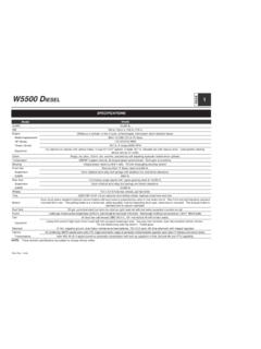
5 Installation of the Upfitter (AUX) Switches and supporting components are NOT a GM Warranty or PDI covered labor cost. The installation of the switches/components are intended to be performed by the upfitter as a part of the overall vehicle upfit and the labor cost associated with that installation be covered in the upfitter s estimate to its customer. Installation, when performed by a GM dealer, the labor charges associated with that install are the responsibility of the customer/vehicle purchaser. Figure 1 Figure 2 UI Bulletin #153c General Motors Upfitter Integration Bulletin #153c P a g e | 3 April 12, 2021 Disclaimer: GM Upfitter Integration Technical Bulletins are intended for use by professional technicians, NOT a "do-it-yourselfer". They are written to inform these technicians of conditions that may occur on some vehicles, or to provide information that could assist in the proper service and/or modification of a vehicle.
6 These properly trained technicians have the equipment, tools, safety instructions, and know-how to do a job properly and safely. If a condition is described, DO NOT assume that the bulletin applies to your vehicle, or that your vehicle will have that condition. Contact GM Upfitter Integration for information on whether the information is applicable your vehicle. Repair/Recommendation: To install the Aux switches, the knee bolster may require replacement or may simply need to have a few fasteners removed (if switches are installed during vehicle assembly refer to the vehicle model sections below for details. NOTE: Prior to reinstalling the replacement Knee Bolster (if applicable) follow the instructions in bulletin. Light Duty(1500)/Service Parts Kit For these vehicle installations the first step is to remove the knee bolster trim panel using the combined service information procedures outlined in the link below, do NOT install the new knee bolster until after performing the steps below.)
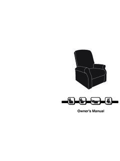
7 Instrument Panel Knee Bolster Replacement While the knee bolster is removed, the Instrument Panel Auxiliary Fuse Block should be mounted, the connector for the switch bank assembly routed and secured, the gray connector to the IP harness connected, the power cable from the battery ran and secured (not yet connected to the battery) and lastly the fuse kit installed in the Battery Fuse Block. The installation of these components is outline in the steps/sections below. Electrical Center mounting/connections: 1. Mount the IP Aux. Fuse block using the 2 screws in the locations circled in RED as shown in figure 3 Electrical Center UI Bulletin #153c General Motors Upfitter Integration Bulletin #153c P a g e | 4 April 12, 2021 Disclaimer: GM Upfitter Integration Technical Bulletins are intended for use by professional technicians, NOT a "do-it-yourselfer".
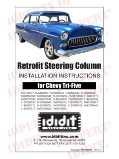
8 They are written to inform these technicians of conditions that may occur on some vehicles, or to provide information that could assist in the proper service and/or modification of a vehicle. These properly trained technicians have the equipment, tools, safety instructions, and know-how to do a job properly and safely. If a condition is described, DO NOT assume that the bulletin applies to your vehicle, or that your vehicle will have that condition. Contact GM Upfitter Integration for information on whether the information is applicable your vehicle. Connect the 14-pin connector Aux Fuse Block to the connector shown in figure 4 (note vehicle is shipped from the assembly plant with a blank connector in place to protect the terminals in the IP Harness. Remove this prior to connecting the connector from the fuse block) Figure 4 2.
9 Route the 16-pin switch bank connector through the opening in the Instrument Panel as shown in figure 5 Power Cable installation/routing: 3. Remove the 4 (circled in red) retaining push pins (only) for the Air Inlet Grill as shown in figure 6 4. Secure the power cable using the new supplied push pins by inserting the push pin through the eyelets on the power cable and into the securing locations for the air inlet grill that were previously removed. The power cable end with ring terminal should be routed (but not yet connected) to the Battery Distribution Unit (BDU) (the fuse block mount to the top of the primary battery). 5. Route the power cable into the cabin as shown in figure 7 (note do not install wire terminal into connector body until after the cable is routed into the cabin Figure 5 UI Bulletin #153c General Motors Upfitter Integration Bulletin #153c P a g e | 5 April 12, 2021 Disclaimer: GM Upfitter Integration Technical Bulletins are intended for use by professional technicians, NOT a "do-it-yourselfer".)
10 They are written to inform these technicians of conditions that may occur on some vehicles, or to provide information that could assist in the proper service and/or modification of a vehicle. These properly trained technicians have the equipment, tools, safety instructions, and know-how to do a job properly and safely. If a condition is described, DO NOT assume that the bulletin applies to your vehicle, or that your vehicle will have that condition. Contact GM Upfitter Integration for information on whether the information is applicable your vehicle. 6. Insert terminal on the power cable into the supplied connector body and connect the connector to the Aux. Fuse block 7. Secure any loose wires under the IP/Steering Column area with nylon wire ties to prevent squeaks/rattle and harness rubbing/chaffing conditions Install switches installed into the new knee bolster trim in the provided cut-out.