Transcription of AHE-100-02S SERVICE MANUAL - Aqua-Hot Heating …
1 SERVICE MANUAL 2011 Aqua-Hot Heating Systems Inc. AHE-100-02S Page 2 2011 Aqua-Hot AHE-100-02S Hydronic Heating System SERVICE MANUAL Rev. B Page 3 2011 Aqua-Hot AHE-100-02S Hydronic Heating System SERVICE MANUAL Rev. B Section 1: Introduction to the Aqua-Hot AHE-100-02S Introduction ..Page 6-7 Danger, Warning, Caution, and Note Box Definitions ..Page 6 Section 2: Aqua-Hot Hydronic Heating System Overview Technical Information ..Page 8 Label Sample ..Page 9 Component Overview ..Page 9-10 Aqua-Hot Operational Flow-Chart ..Page 11 Section 3: Interior Switch Panel Diesel-Burner Switch ..Page 12 Electric Element Switch ..Page 12 Engine Preheat Switch ..Page 12 Section 4: Exhaust System Requirements Exhaust System Requirements ..Page 13 Section 5: Aqua-Hot Components Control Thermostat - Diesel Burner ..Page 14-15 Control Thermostat - Electric Element ..Page 16-17 High Limit Thermostat.
2 Page 18 High Limit Thermostat .. Page 19 Check Valves ..Page 20-21 Tempering Valve ..Page 22-23 Circulation Pumps C, B & A ..Page 24-25 Stir Pump ..Page 26 Engine Preheat Pump ..Page 27-28 Interior Zone Relay - Interior Heat Exchanger Fans/Zone Pumps ..Page 29-30 Electric Heating Element ..Page 31-32 Table of Contents Page 4 2011 Aqua-Hot AHE-100-02S Hydronic Heating System SERVICE MANUAL Rev. B Section 6: Diesel-Burner Overview .. Page 33-38 Plate .. Page 33 Diesel-Burner Overview .. Page 33-34 Diesel-Burner Operational Flow Chart .. Page 35 Diesel-Burner Operational Overview .. Page 36-38 Section 7: Detaching and Reattaching the Diesel-Burner Detaching the Diesel-Burner .. Page 39-42 Reattaching the Diesel-Burner .. Page 43-44 Section 8: Diesel-Burner Components / Trouble Shooting Troubleshooting Flow Chart .. Page 45-49 Motor .. Page 50-53 Flame Sensor .. Page 54-55 Ignition Electrodes.
3 Page 56-57 Fuel Nozzle .. Page 57-58 Fuel Solenoid .. Page 59 Fuel Pump .. Page 60-62 Bearings .. Page 63-65 Ignition Coil .. Page 66-67 Controller .. Page 68-69 Section 9: General Troubleshooting If the Aqua-Hot is Black Smoking .. Page 70 If the Aqua-Hot is Blue/White Smoking .. Page 71 If one of the Aqua-Hot s Heating Zones will not get hot .. Page 72 If there is a lack of domestic continuous hot water .. Page 73 If there is antifreeze leaking .. Page 74-75 Appendix A: Wiring Diagram ..Page 76-77 Appendix B: BLEEDING THE INTERIOR Heating ZONE CIRCULATION PUMP ..Page 78-82 Appendix C: Fuel Pressure check and Adjustment ..Page 83-86 Appendix D: Extreme Cold Weather Operation ..Page 87-88 Appendix E: Aqua-Hot Annual Maintenance .. Page 89-102 Appendix F: Winterization Process .. Page 103 Table of Contents Page 5 2011 Aqua-Hot AHE-100-02S Hydronic Heating System SERVICE MANUAL Rev. B This Page Left Blank Intentionally Page 6 2011 Aqua-Hot AHE-100-02S Hydronic Heating System SERVICE MANUAL Rev.
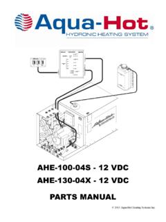
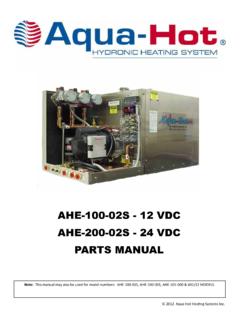
4 B SECTION 1: INTRODUCTION TO THE Aqua-Hot AHE-100-02S This SERVICE and parts MANUAL is designed to aid trained and qualified SERVICE technicians with the process of troubleshooting and servicing the Aqua-Hot AHE-100-02S Hydronic Heating sys-tem. The Aqua-Hot AHE-100-02S Heating system features a 12 Volt-DC powered diesel-burner and a 120 Volt-AC, 1650 Watt electric Heating element. These two Heating sources are used in conjunction with an antifreeze/water Heating solution in order to provide a continuous supply of domestic hot wa-ter, interior/fresh water tank Heating , independent interior zone Heating , and engine preheating. Be sure to reference Figures 3 for a complete component overview. Please note that all Danger, Warning, Caution, and Note box-es, appearing as needed throughout this MANUAL , must be reviewed and adhered to during any SERVICE procedure in order to avoid potential hazards, which could result in injury, product damage, or property damage.
5 Should additional assistance be needed, please contact the technical support department at 1-800-685-4298, Monday through Friday, between the hours of 7:00 AM and 4:00 PM Mountain Standard Time. Danger, Warning, Caution, and Note Boxes: Danger, Warning, Caution, and Note boxes appear through-out this MANUAL as a means of alerting the SERVICE technician to important information. INDICATES THAT PERSONAL INJURY IS LIKELY OR IMMINENT. Indicates that serious damage to the heater will occur and personal injury is possible as well. Indicates that damage to the heater is possible. NOTE: Indicates information that requires special atten-tion by the SERVICE technician Understanding the Aqua-Hot AHE-100-02S Major Systems: The basis for the Aqua-Hot Heating system s functionality is the antifreeze and water Heating solution, which is comprised of water that is distilled, de-ionized, or soft, as well as anti-freeze. Through this solution s ability to maintain and trans-fer heat, the Aqua-Hot s three major systems: the domestic water system, engine preheat system, and interior Heating system, are able to function effectively.
6 This antifreeze and water Heating solution is contained within the Aqua-Hot s boiler tank and is heated by the diesel-burner when its oper-ating criteria are met and/or the electric Heating element when its operating criteria are met. In order for the diesel-burner to be considered as a Heating source by the Aqua-Hot , it must have an adequate fuel supply, receive power from the fuse block, and be selected as a Heating source from the inte-rior switch panel. In order for the electric Heating element to be considered as a Heating source by the Aqua-Hot , it must receive power from either a generator or from shore power and be selected as a Heating source. Once the antifreeze and water Heating solution achieves operating temperature (as determined by the Aqua-Hot s control thermostat), the do-mestic water system, the engine preheat system, and the inte-rior Heating system are permitted to operate as needed.
7 Domestic Hot Water System: When hot water is requested, domestic water from the motor home s fresh water tank is transported through a copper coil around the Aqua-Hot s boiler tank where heat is transferred from the heated antifreeze and water Heating solution to the domestic water flowing through the copper coil. The heated domestic water then flows through the tempering valve to be mixed with cool water from the fresh water tank to achieve an appropriate temperature before it flows to the faucet re-questing hot water. Page 7 2011 Aqua-Hot AHE-100-02S Hydronic Heating System SERVICE MANUAL Rev. B SECTION 1: INTRODUCTION TO THE AHE-100-02S Engine Preheat System: The engine preheat system is responsible for Heating the mo-tor home s engine block in order to make it easier to start-up when cool weather conditions exist. When the engine preheat system is activated via the interior switch, the motor home s engine coolant is circulated through a dedicated copper coil in the Aqua-Hot s boiler tank, where heat from the antifreeze and water Heating solu-tion is transferred to the motor home s engine coolant.
8 The heated engine coolant is then transported back to the engine where it transfers the heat to the engine to gradually warm it. Additionally, the Aqua-Hot includes a motor-aide feature, which uses the circulation of the motor home s engine to transport the engine s coolant from the Aqua-Hot s boiler tank to the motor home s warm engine and back to the boiler tank. Through this process, the boiler tank is kept heated, which reduces the time required to bring the tank to operat-ing temperature for interior heat and continuous domestic hot water. This motor-aide feature is part of the engine preheat-ing feature and plumbing system, and requires no action on the user s behalf to function. Interior Heating System: The interior Heating system is responsible for providing heat to the motor home s interior in order to maintain the temper-ature at a comfortable level. For interior Heating , it is the room thermostats that trigger the Aqua-Hot s interior Heating system.
9 When a thermostat rec-ognizes that heat is required in a particular area, it sends a signal to the Aqua-Hot s corresponding zone relay. The Zone Relay responds by activating the circulation pump for that zone, which sends the heated antifreeze and water heat-ing solution through the Heating Loop corresponding to the zone requesting heat. The fans on the heat exchangers in the zone calling for heat are also activated; therefore, as the heat-ed solution flows over the heat exchanger s fins, the heat is transferred to those fins and dispersed into the interior of the motor home by the fans. Until the thermostat signals that heat is no longer required, the Aqua-Hot will continue to send the heated antifreeze and water solution through the loop, which returns the cooled solution to the Aqua-Hot s boiler tank to be re-heated before being sent back through the loop again. This process continues until the pre-set tem-perature of the interior is reached, and the interior room ther-mostat signals the electronic controller that heat is no longer required.
10 AC Circuit: Although the diesel-burner is the primary Heating source for the Aqua-Hot and is necessary for providing continuous do-mestic hot water, an alternate heat source exists for moderate temperatures, which functions with an AC circuit. Whenever the motor home is connected to an AC power source - plugged into shore power or using a generator, the Aqua-Hot s electric Heating element has the ability to function in order to provide heat for the boiler tank. When the antifreeze and water Heating solution falls below operating temperature (as determined by the control thermo-stat), the control thermostat closes, and allow AC power to flow to the electric Heating element. When the electric heat-ing element receives power, it becomes active and supplies heat to the boiler tank until operating temperature is reached. Page 8 2011 Aqua-Hot AHE-100-02S Hydronic Heating System SERVICE MANUAL Rev. B SECTION 2: Aqua-Hot AHE-100-02S OVERVIEW Diesel-Burner, Heat Input (Firing Rate).