Transcription of AIA CAD Layer Guidelines - Autodesk
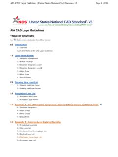
1 NATIONAL CAD STANDARD FOR ARCHITECTURE, ENGINEERING, & CONSTRUCTION (A/E/C) VERSION 2005. NATIONAL INSTITUTE OF BUILDING SCIENCES AIA CAD Layer Guidelines : National CAD Standard Version 3 The American Institute of Architects 1735 New York Avenue, NW Washington, DC 20006-5292 (800) 242-3837 NATIONAL CAD STANDARD FOR ARCHITECTURE, ENGINEERING, & CONSTRUCTION (A/E/C) VERSION 2005. NATIONAL INSTITUTE OF BUILDING SCIENCES The American Institute of Architects 1735 New York Avenue, NW Washington, DC 20006-5292 2005 The American Institute of Architects All rights reserved Published 2005 Printed in the United States of America Previous editions of AIA CAD Layer Guidelines : 1990: CAD Layer Guidelines (1st edition, AIA Press) 1997: CAD Layer Guidelines (2nd edition, AIA Press) 2002: AIA CAD Layer Guidelines : National CAD Standard Version 2 To order additional copies of the National CAD Standard, go to No part of this publication may be reproduced, either in whole or in part, or stored in a retrieval system, or reproduced by mechanical or electronic photocopying, recording, or other means now known or hereafter invented, without the express written permission of the publisher.
2 NATIONAL CAD STANDARD FOR ARCHITECTURE, ENGINEERING, & CONSTRUCTION (A/E/C) VERSION 2005. NATIONAL INSTITUTE OF BUILDING SCIENCES TABLE OF CONTENTS CLG-i Table of Contents INTRODUCTION CLG-1 A Brief History of CAD Layer 1 New in Version .. 3 Layer NAME FORMAT Hierarchy of Data Fields .. CLG-4 Before You 4 Discipline Designator, Level 1 .. 5 Discipline Designator, Level 2 .. 6 Major Group .. 7 Minor Group .. 7 Status (Phase) .. 8 Layer LIST Drawing View Layer List .. CLG-9 Annotation Layer 11 General Layer List .. 13 Hazardous Materials Layer List .. 15 Survey and Mapping Layer 17 Geotechnical Layer List .. 23 NATIONAL CAD STANDARD FOR ARCHITECTURE, ENGINEERING, & CONSTRUCTION (A/E/C) VERSION 2005. NATIONAL INSTITUTE OF BUILDING SCIENCES TABLE OF CONTENTS CLG-ii Civil Works Layer List .. 25 Civil Layer 27 Landscape Layer List .. 35 Structural Layer List .. 39 Architectural Layer List.
3 43 Interiors Layer 47 Equipment Layer List .. 49 Fire Protection Layer List .. 53 Plumbing Layer 55 Process Layer 57 Mechanical Layer List .. 61 Electrical Layer List .. 69 Telecommunications Layer List .. 77 Resource Layer List .. 79 Other Disciplines Layer List .. 81 Contractor / Shop Drawing Layer List .. 83 Operations Layer 85 COMMENTARY: NCS AND ISO 13567 CLG-87 Field Codes .. 88 Field Codes and Language .. 88 ISO 13567 Conformance .. 89 Field Names and Definitions .. 90 Discipline Designator vs. Agent 90 Agent Responsible and Professional 90 Discipline Designator and the Building Life Cycle .. 91 Discipline Designator and ISO 13567 Conformance .. 91 NATIONAL CAD STANDARD FOR ARCHITECTURE, ENGINEERING, & CONSTRUCTION (A/E/C) VERSION 2005. NATIONAL INSTITUTE OF BUILDING SCIENCES TABLE OF CONTENTS CLG-iii Field Code 92 NCS and ISO Implementation Options .. 93 NCS and ISO Implementation Guidelines .
4 94 NATIONAL CAD STANDARD FOR ARCHITECTURE, ENGINEERING, & CONSTRUCTION (A/E/C) VERSION 2005. NATIONAL INSTITUTE OF BUILDING SCIENCES INTRODUCTION CLG-1 Introduction Overview Virtually all vector-based CAD systems support the concept of layers. This function allows building design information to be organized in a systematic fashion, facilitates the visual display of the information on a computer screen, and allows the information to be efficiently converted to the conventional print media of drawings. Efficient use of layers can reduce document preparation time and improve document coordination. Organizing data by layers allows a single CAD file to contain a wealth of information about a building or facility. By turning selected layers on or off, data can be created, reviewed and edited according to a hierarchy that simulates the physical organization of building systems, the relative position of building elements, or the sequence of construction.
5 A Brief History of CAD Layer Guidelines The American Institute of Architects published the first edition of CAD Layer Guidelines in 1990. The early success of the first edition and rapidly evolving technology resulted in the second edition being published in 1997. The most significant change between the first and second editions was the elimination of the short Layer name format and the adoption of the long Layer name format as a single standard. The second edition also included additional Layer field codes for remodeling projects, added new discipline designations for interiors, telecommunications, and other disciplines, and improved the method of organizing drawing annotation. In July 1997, the AIA agreed to incorporate CAD Layer Guidelines into the emerging National CAD Standard ( NCS), a project of the National Institute of Building Sciences (NIBS).
6 The AIA and NIBS were joined in that effort with the Construction Specifications Institute (CSI) and the (then-known) Tri-Service CADD/GIS Technology Center of the Army Corps of Engineers. CSI and Tri-Service agreed to incorporate their own publications into the NCS, the Uniform Drawing System and the Plotting Guidelines , respectively. These four NATIONAL CAD STANDARD FOR ARCHITECTURE, ENGINEERING, & CONSTRUCTION (A/E/C) VERSION 2005. NATIONAL INSTITUTE OF BUILDING SCIENCES INTRODUCTION CLG-2 constituent publishers, as they came to be known, were joined by a number of building design and construction industry organizations in developing and publishing the NCS. In March 1999, the National CAD Standard Project Committee formally accepted CAD Layer Guidelines , Second Edition (with minor amendments) as a constituent document of the National CAD Standard, Version , published in July 1999.
7 The NCS Project Committee immediately set to work on publication of Version , which was published in 2002. Considerable confusion resulted from the lack of alignment between the Second Edition of CAD Layer Guidelines and Version of the National CAD Standard. Because CAD Layer Guidelines , Second Edition was published before, and later incorporated into, the National CAD Standard, Version , this could not be avoided. With publication of the National CAD Standard, Version , this problem was corrected by giving the constituent document an entirely new name. For the first time, AIA became part of the title of the publication, and the numbered editions were abandoned. As a result, this publication is known as AIA CAD Layer Guidelines : NCS Version No doubt some confusion will still arise between the NCS Version and the old CAD Layer Guidelines , Second Edition, but the problem should be resolved with the publication of the new NCS, Version Version 2 AIA CAD Layer Guidelines , version 2, was designed and formatted to match its companion document, CSI's Uniform Drawing System.
8 It was also carefully coordinated with that document, so that the two function as a whole. Additions and improvements to version 2 of AIA CAD Layer Guidelines : Incorporation of NCS v1 amendments, including the change from a four-character to a single character Status field. An expanded Layer Format that includes a two-character discipline designator and a second optional Minor Group. An expanded Drawing View Layer List for users with a need to organize data by drawing type rather than by building system. Expanded Layer Lists for Civil, Structural, Mechanical, Plumbing, and Telecommunications Disciplines. NATIONAL CAD STANDARD FOR ARCHITECTURE, ENGINEERING, & CONSTRUCTION (A/E/C) VERSION 2005. NATIONAL INSTITUTE OF BUILDING SCIENCES INTRODUCTION CLG-3 New Discipline Designators for Survey/Mapping, Geotechnical, Civil Works, Process, and Operations Disciplines. An entirely new Layer List for the Survey/Mapping Discipline.
9 New Annotation Minor Groups, and a new free agent rule permitting Annotation Minor Groups to modify any Major Group. Clarification of the existing free agent rule, emphasizing that any reasonable combination of Discipline Designator, Major Group and Minor Group is permitted. New rules and a detailed Commentary to facilitate conformance with the ISO CAD Standard. New in Version 3 Highlights of revisions and additions to Version 3 include the following: User-defined Minor Group field codes may now be four alphabetic and/or numeric characters (0 9) and/or ~ . Additions to the Process Layer List allow users to define layers by individual systems or groups of systems. Expanded the Landscape Layer List. New Major and Minor Groups added to the Equipment, Mechanical, and Interior Layer Lists. Equipment Layer added to the Fire Protection Layer List. NATIONAL CAD STANDARD FOR ARCHITECTURE, ENGINEERING, & CONSTRUCTION (A/E/C) VERSION 2005.
10 NATIONAL INSTITUTE OF BUILDING SCIENCES Layer NAME FORMAT CLG-4 Layer Name Format Hierarchy of Data Fields The Layer name format is organized as a hierarchy. This arrangement allows users to select from a number of options for naming layers according to the level of detailed information desired. Layer names consist of distinct data fields separated from one another by dashes. A detailed list of abbreviations, or field codes, is prescribed to define the content of layers. Most field codes are mnemonic English abbreviations of construction terminology that are easy to remember. There are four defined Layer name data fields: Discipline Designator, Major Group, two Minor Groups, and Status. The Discipline Designator and Major Group fields are mandatory. The Minor Group and Status fields are optional. Each data field is separated from adjacent fields by a dash ( - ) for clarity.