Transcription of Air Cooled Dry coolers and Condensers - Acare
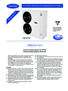
1 Air Cooled Dry coolers and CondensersAir Cooled 09 GDV dry coolers and 09 LDV Condensers aredesigned for commercial and industrial cooling and refrigera-tion plants. Due to its construction, the range is especiallysuitable when high capacity relative to available space, lowenergy consumption or low noise levels are sizes with nominal capacities from 146 to 1638 kW(water, EN 1048) for liquid use and with nominalcapacities from 170 to 1812 kW for condenser use(R404A/ T1 15 K, EN 327) Performance data according to Eurovent Rating Standards7/C/002 and 7/C/003 Two fan sizes and five fan speed alternatives to reach therequired sound level Casing made of hot dip galvanised steel Complete fan control systems available, based on fanspeed regulation (SVC) or on stepped fan starting cycle(Step Control) Pro-Dialog option is available for dry coolers matching30RW water Cooled chillers and for air Cooled condensersmatching 30 RWA & 30 HZV condenserless chillers Product selection with the Polar Power selection programTechnical dataThe heat transfer section is made of copper tubes and alumi-nium fins.
2 Standard fin spacing is mm. As an option,aluminium fins with epoxy coating are also extend the working life of the coil in urban and coastalenvironments. The capacity correction factor for epoxy-coatedaluminium fins is heat transfer section can be multi-circuited or equippedwith a sub-cooling circuit. During short loading peaks a waterspraying system can considerably increase the heat coil of a dry cooler is equipped with draining and ventingnipples but the standard version cannot be totally take this into consideration when specifying the freez-ing point of the heat transfer fan chambers are separated crosswise. The units areequipped with lifting lugs, and smaller models have liftingpoints for a forklift (see lifting instructions in the dimensionaldrawing).When placing the units, please ensure that the air flow isneither obstructed nor recirculated. If there are several coolers ,you can reduce the spacing between units by installing themon a higher mounting base.
3 Please check the placing ofmultiple coolers with our manual including installation and service instructions isshipped with each and 09 LDVN ominal cooling capacities for dry coolers 146 to 1638 kW (water)and for Condensers 170 to 1812 kW (R404A)Carrier is participating inthe Eurovent CertificationProgramme. Products areas listed in the EuroventDirectory of designation09 GDVE-184-3 12-10-9-50-136DN65-D09 GDV = Dry cooler09 LDV = CondenserE = Special model184 = Size3 = Number of fans12 = Fan diameter10 = Fan speed rpm6 = r/s8 = r/s10 = r/s12 = r/s16 = r/s9 = Power supply8 = 230 V-3 ph-50 Hz9 = 400 V-3 ph-50 HzAdditional markings for dry cooler 09 GDV:136DN65136 = Number of circuitsDN = Tube connection typeDN = Flange R = Outer thread125 = Connection sizeOptions: D = water spraying system S = vibration dampers Ep = epoxy coated aluminium fins SC = step control (see separate brochure) SVC = fan speed control with frequency converter(see separate brochure) Sub = sub-cooling block J = multi-circuited condenser number of passesfrom up to down (J:1:2.)
4 1)FansThe axial fans are equipped with squirrel cage motors builtaccording to IEC standards, with IP 54 standard degree ofprotection and class F insulation. The motors are providedwith shaft seals and drainage holes. Allowed air outlet tem-perature for standard motors is at least + 60 C. Suitability forhigher temperatures has to be checked separately. The motorsare wired to the fans safety switches (IP 65) on the end ofthe standard motors are suitable for 380 V-3 ph-50 V-3 ph-50 Hz. With delta connection they are suitablefor 230 V-3 ph-50 Hz (except the motor 11 kW, r/s).For other power supplies, the fans must be specified as fan power input at + 20 C is given in the performancedata tables. The full load current is given at a temperatureof 30 C for specifying the overload protector. The currentvalue changes according to air density. This data may alsovary due to changes in motor types; therefore the overloadprotectors should have a +/ 20 % adjustment ensure the lifetime of the fans, they shall be started for atleast hours once a transfer capacitiesThe capacities, air flows, sound power levels and liquidpressure drop (dry cooler) shown in the Polar Power selectionsoftware and in the tables in this brochure are certified byEurovent Certify-All certification, and are verified by tests(EN 1048, EN 327) in independent performance data of the dry coolers are given for water+40/35 C, air entering temperature + 25 C according toEurovent, and for ethylene glycol 40 %, + 42/36 C, airentering temperature + 27 nominal heat transfer capacities of the Condensers aregiven for refrigerant R404A, with temperature difference15 K and air entering temperature + 25 C.
5 The performancedata is given at the sea level and with normal is the A-weighted sound power level [dB(A)]. TheA-weighted sound pressure level Lpa [dB(A)] is given at fandeck height and at a distance of 10 meters from the end of theunit, with the unit in free field conditions over one reflectiveplane (hemisphere).SelectionThe preliminary product selection can be made using the tablesin this leaflet. The condenser capacities for the required refriger-ant and temperature difference can be calculated with the helpof the correction factors. The exact cooler selection and drycooler dimensioning is made by Polar Power software, whichis available on selection is based on required capacity, temperatures,noise level at desired point and refrigerant or liquid program gives the most suitable models with heat transfercapacities, connection data, noise levels by octave bands,operating cost calculations and dimensional r/sPoles16121086 Power kWFLC (full load current) A A APlacing CAP Flow LpaLwaCAPFlow LpaLwaCAPFlow LpaLwaCAPFlow LpaLwaCAPFlow LpaLwa09 LDVof fans kWm3/s dB(A) dB(A) kWm3/s dB(A) dB(A) kWm3/s dB(A) dB(A) kWm3/s dB(A) dB(A) kWm3/s dB(A) dB(A)
6 Diameter 1240 mmCorrection factors for different refrigerantsCAP = Nominal capacityFlow = Air flowLpa = Sound pressure levelLwa = Sound power levelPerformance data 09 LDVFan diameter 914 mmR404A, T1 15 K, EN 327400 V-3 ph-50 HzTemperature difference T1 [K]:Refrigerant810121415161820R404A / r/sPoles16121086 Power kWFLC (full load current) A A11 A 17 A27 APlacing CAP Flow LpaLwaCAPFlow LpaLwaCAPFlow LpaLwaCAPFlow LpaLwaCAPFlow LpaLwa09 LDVof fans kWm3/s dB(A) dB(A) kWm3/s dB(A) dB(A) kWm3/s dB(A) dB(A) kWm3/s dB(A) dB(A) kWm3/s dB(A) dB(A)100-21x2206 102681041310 11975111 Capacities depend on the tubing. The exact capacity is given by the selection r/sPoles16121086 Power kWFLC (full load current) APlacing CAP Flow LpaLwaCAPFlow LpaLwaCAPFlow LpaLwaCAPFlow LpaLwaCAPFlow LpaLwa09 GDVof fans kWm3/s dB(A) dB(A) kWm3/s dB(A) dB(A) kWm3/s dB(A) dB(A) kWm3/s dB(A) dB(A) kWm3/s dB(A) dB(A) diameter 1240 mmCAP = Nominal capacityFlow = Air flowLpa = Sound pressure levelLwa = Sound power levelPerformance data 09 GDVFan diameter 914 mmAir on +25 C, water +40/35 C, EN 1048400 V-3 ph-50 HzFan r/sPoles16121086 Power kWFLC (full load current) A A11 A 17 A27 APlacing CAP Flow LpaLwaCAPFlow LpaLwaCAPFlow LpaLwaCAPFlow LpaLwaCAPFlow LpaLwa09 GDVof fans kWm3/s dB(A) dB(A) kWm3/s dB(A) dB(A) kWm3/s dB(A) dB(A) kWm3/s dB(A) dB(A) kWm3/s dB(A)
7 DB(A) 102681041237 11975111 Capacities depend on the tubing. The exact capacity is given by the selection r/sPoles16121086 Power kWFLC (full load current) APlacing CAP Flow LpaLwaCAPFlow LpaLwaCAPFlow LpaLwaCAPFlow LpaLwaCAPFlow LpaLwa09 GDVof fans kWm3/s dB(A) dB(A) kWm3/s dB(A) dB(A) kWm3/s dB(A) dB(A) kWm3/s dB(A) dB(A) kWm3/s dB(A) dB(A)100-42x2141 diameter 1240 mmCAP = Nominal capacityFlow = Air flowLpa = Sound pressure levelLwa = Sound power levelPerformance data 09 GDVFan diameter 914 mmAir on +27 C, ethylene glycol 40% +42/36 C 400 V-3 ph-50 HzFan r/sPoles16121086 Power kWFLC (full load current) A A11 A 17 A27 APlacing CAP Flow LpaLwaCAPFlow LpaLwaCAPFlow LpaLwaCAPFlow LpaLwaCAPFlow LpaLwa09 GDVof fans kWm3/s dB(A) dB(A) kWm3/s dB(A) dB(A) kWm3/s dB(A) dB(A) kWm3/s dB(A) dB(A)
8 KWm3/s dB(A) dB(A)100-21x2174 11975111 Dimensional drawingsFan 914 Fan 124009 LDV/GDVMax. FixingNWIV 2)SAWater spraying system DdimensionspointsWFTCA [ mm ]L [ mm ] 1)[ kg ][ l ][ m2 ][ l/min. 3 bar ] [ mm ] tube connection sizes1) Connections on both ends2) Internal volume with maximum header sizeDimension and weightSA = Surface areaIV = Internal volumeWF = Water flowTC = Tube connectionNW = Net r/s, r/sNo. of09 LDVGasLiquidGasLiquidGasLiquidGasLiquidc ircuits1002*422*422*422*422*422*422*422* 422*151102*422*422*422*422*422*422*422*4 22*161202*422*422*422*422*422*422*422*42 2*251482*422*422*422*422*422*422*422*422 *181682*422*422*422*422*422*422*422*422* 251842*542*542*542*542*542*542*542*542*3 71982*542*542*542*542*542*542*542*542*25 2222*542*542*542*542*542*542*542*542*332 462*542*542*542*542*632*632*632*632*5025 02*542*542*542*542*542*542*542*542*37280 2*542*542*542*542*542*542*542*542*503102 *542*542*632*632*632*632*632*632*503002* 542*542*542*542*542*542*542*542*373302*6 32*632*632*632*632*632*632*632*503702*63 2*632*632*632*632*632*632*632*7509 LDV/GDVN [mm]
9 On Totally Chlorine Free in locating the products, take care that the air flow is neither obstructed nor the heat exchanger is not installed on a higher mounting base, there must be a free spaceof at least 1 meter around all sides of each Fnc ECR, Vantaa, FinlandTel. +358 9 894 41 Order No. , supersedes No. to changes without prior cover photo is solely for illustration purposes, and is not contractually member of theUnited TechnologiesCorporation Family.


