Transcription of AIR-COOLED SCREW LIQUID CHILLERS - Johnson Controls
1 AIR-COOLED SCREW LIQUID CHILLERSINSTALLATION, OPERATION, MAINTENANCES upersedes: (119)Form (819)HFC-134A OR R-513 ALD15045150 500 TONS525 1750 KW2 compressor 50 HZ AND 60 HZMODEL YVAA STYLE AAIR- cooled SCREW LIQUID CHILLERS WITHVARIABLE SPEED DRIVEFRAME SIZES 015 052035-23219-100 Issue Date: August 19, 2019 Johnson CONTROLS2 FORM ISSUE DATE: 08/19/2019 This equipment is a relatively complicated apparatus. During rigging, installation, operation, maintenance, or service, individuals may be exposed to certain com-ponents or conditions including, but not limited to: heavy objects, refrigerants, materials under pressure, rotating components, and both high and low voltage.
2 Each of these items has the potential, if misused or handled improperly, to cause bodily injury or death. It is the obligation and responsibility of rigging, instal-lation, and operating/service personnel to identify and recognize these inherent hazards, protect themselves, and proceed safely in completing their tasks. Failure to comply with any of these requirements could result in serious damage to the equipment and the property in IMPORTANT!READ BEFORE PROCEEDING!GENERAL SAFETY GUIDELINES which it is situated, as well as severe personal injury or death to themselves and people at the document is intended for use by owner-authorized rigging, installation, and operating/service personnel.
3 It is expected that these individuals possess independent training that will enable them to perform their assigned tasks properly and safely. It is essential that, prior to performing any task on this equipment, this individual shall have read and understood the on-product labels, this document and any referenced materials. This in-dividual shall also be familiar with and comply with all applicable industry and governmental standards and regulations pertaining to the task in SYMBOLSThe following symbols are used in this document to alert the reader to specific situations:Indicates a possible hazardous situation which will result in death or serious injury if proper care is not a potentially hazardous situa-tion which will result in possible injuries or damage to equipment if proper care is not a hazard which could lead to damage to the machine, damage to other equipment and/or environmental pollu-tion if proper care is not taken or instruc-tions and are not additional information useful to the technician in completing the work being performed wiring, unless specified as an optional connection in the manufacturer s product line, is not to be connected inside the control cabinet.
4 Devices such as relays, switches, transducers and Controls and any external wiring must not be installed inside the micro panel. All wiring must be in accor-dance with Johnson Controls published specifications and must be performed only by a qualified electrician. Johnson Controls will NOT be responsible for damage/problems resulting from improper connections to the Controls or application of improper control signals. Failure to follow this warn-ing will void the manufacturer s warranty and cause serious damage to property or personal CONTROLS3 FORM DATE: 08/19/2019In complying with Johnson Controls policy for con-tinuous product improvement, the information con-tained in this document is subject to change without notice.
5 Johnson Controls makes no commitment to update or provide current information automatical-ly to the manual or product owner. Updated manu-als, if applicable, can be obtained by contacting the nearest Johnson Controls Service office or ac-cessing the Johnson Controls QuickLIT website at is the responsibility of rigging, lifting, and operat-ing/ service personnel to verify the applicability of these documents to the equipment. If there is any ques-tion regarding the applicability of these documents, rigging, lifting, and operating/service personnel should verify whether the equipment has been modified and if current literature is available from the owner of the equipment prior to performing any work on the BARSR evisions made to this document are indicated with a line along the left or right hand column in the area the revision was made.
6 These revisions are to technical in-formation and any other changes in spelling, grammar or formatting are not OF THIS DOCUMENTASSOCIATED LITERATUREMANUAL DESCRIPTIONFORM NUMBERE quipment Pre-Startup and Startup Style A Frame Size 015 - 027, 2 compressor 60 Hz (150-350 Tons)YVAA Style A Frame Size 054 - 098, 2 compressor 50 Hz (525-950 KW) Manufactured before April Style A Frame Size 015 - 052, 2 compressor 50 & 60 Hz (150-500 Tons) (Manufactured after April 2012 to before September 2014) Style B Frame Size 015 - 052, 2 compressor 50 & 60 Hz (150-500 Tons) (Manufactured after September 2014) Control/VSD Cabinet contains lethal high AC and DC voltages. Before per-forming service inside the cabinet, remove the AC supply feeding the chiller and verify using a non-contact voltage DC voltage on the VSD DC Bus will take 5 minutes to bleed off, after AC power is removed.
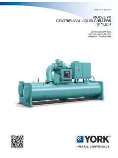
7 Always check the DC Bus Voltage with a Voltmeter to assure the capacitor charge has bled off before working on the short out the DC Bus to dis-charge the filter place loose tools, debris, or any objects inside the Control Panel/VSD allow the Control Panel VSD Cabinet doors to remain open if there is a potential for rain to enter the panel. Keep doors closed and assure all latches are engaged on each door unless the unit is being lockout the disconnect supply-ing AC to the 1L Line Inductor will reach operating temperatures of over 150 C (300 F.) DO NOT open panel doors during operation. Assure the inductor is cool whenever working near the inductor with power CONTROLS4 FORM ISSUE DATE: 08/19/2019 ASHRAE Compliant LD23523aUNIT NOMENCLATUREBase Product TypeYVAA3 AXX46 ALevel / RefrigerantA = Refrigerant R-134aB = Refrigerant R-513 AVoltage17 = 200 / 3 / 6028 = 230 / 3 / 6040 = 380 / 3 / 6042 = 400 / 3 / 6046 = 460 / 3 / 6050 = 380-415 / 3 / 5058 = 575 / 3 / 60021AY = YORKV= Variable Speed ScrewAA = Air cooled Design SeriesConfiguration3 = Condenser CodeX = Evaporator CodeX = compressor CodeX = Condenser Fan & Sound Kit CodeDevelopment Level(Engineering Changeor PIN) Frame SizeJOHNSON CONTROLS5 FORM DATE.
8 08/19/2019 TABLE OF CONTENTSSECTION 1 - GENERAL chiller INFORMATION AND SAFETY ..11 Introduction ..11 Warranty ..11 Quality Assurance and Safety ..12 Fluorinated Greenhouse Gases ..12 Responsibility for Safety ..12 About This of Equipment ..12 SECTION 2 - PRODUCT DESCRIPTION ..15 General System Description ..15 Semi-Hermetic YORK Twin- SCREW Compressors ..17 Evaporator ..17 Condenser ..17 Refrigerant Circuit ..17 Electrical ..17 Building Automation System Capabilities ..18 Microcomputer Control Center ..18 Accessories and Options ..19 Fan Options ..19 Condenser Coils ..19 SECTION 3 - RIGGING, HANDLING, AND STORAGE ..23 Lifting Weights ..23 Delivery and Storage ..23 Inspection ..24 Moving the chiller ..24 Unit Removal from Shipping Container.
9 24 Lifting Using Lugs ..24 Lifting Using Shackles ..24 SECTION 4 - INSTALLATION ..35 Location Requirements ..35 Outdoor Installations ..35 Location Clearances ..35 Vibration Isolators ..37 Shipping Braces ..37 Chilled LIQUID Piping ..37 Evaporator Pressure Drop ..38 Water Treatment ..40 Pipework Arrangement ..40 Minimum Water Volume ..40 Leaving Water Temperature Out of Range ..40 Thermal Storage ..41 Variable Primary Flow ..41 Connection Types and Sizes ..41 Evaporator Connections ..41 Refrigerant Relief Valve Piping ..43 Electrical Connection ..43 Power Wiring ..44 Johnson CONTROLS6 FORM ISSUE DATE: 08/19/2019 TABLE OF CONTENTS (CONT'D)Power Supply Wiring ..44115 VAC Control Supply Transformer ..44 Control Wiring.
10 44 Volts Free Contacts ..45 System Inputs ..45 Power Supply Wiring ..46 Customer Control Wiring ..48 Thermal Dispersion Flow Switch Connections ..49 SECTION 5 - TECHNICAL DATA ..63 Elastomeric Isolator Installation ..90 Elastomeric Isolator Specifications ..91 One Inch Deflection Isolator Installation ..92 One Inch Deflection Spring Isolator Specifications ..93 Two Inch Deflection Isolator Installation and Adjustment ..94 Two Inch Deflection, Restrained Spring Isolator Specifications ..95 SECTION 6 - COMMISSIONING ..97 Preparation ..97 First Time Start Up ..99 General Operation ..100 SECTION 7 - OPERATION ..101 Operating Controls ..101 Basic Operating Sequence ..103 Unit Warning ..103 Microboard (331-03478-xxx).