Transcription of Air Cylinders’ Drive System Full ... - SMC株式会社
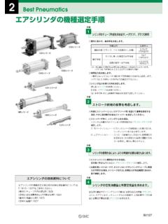
1 How to Read the GraphThis graph shows the full stroke time and stroke end velocity when a cylinder Drive System is composed of the most suitable the graph shown below, various load ratio and full stroke time which corresponds to stroke and terminal velocity are indicated for every cylinder bore the cylinder bore size is , its stroke is L, and load ratio is d%, full stroke time t is obtained, as an arrow mark q, by reading the value on the abscissa over the point at which the ordinate L hits the full stroke line (red line) of d%.
2 Terminal velocity u is obtained, as an arrow mark w, by reading the value on the abscissa below the point at which the ordinate L hits the terminal velocity line (blue line) of d%. Full stroke time (t)Stroke end velocity (u) air cylinders Drive SystemFull Stroke Time & Stroke End VelocityPressureCylinder orientationSpeed controllerLoad factorPiping MPaCJ2 series, CM2 series, CQ2 seriesMB series, CQ2 seriesCS1 series, CS2 seriesVertically upwardMeter-out, connected with cylinder directly, needle fully opened((Load mass x )/Theoretical output) x 100%1 m2 m3 mConditionsExampleStroke (L)Full stroke timeStrokeSpeedTime (sec)(mm)SOL.
3 ON OFFS trokeStroke end velocityqwd%d%Glossary of Terms: cylinder s Motion Characteristics(1) Piston start-up time It is the time between the solenoid valve is energized (de-energized) and the piston (rod) of a cylinder starts traveling. The accurate judgement is done by the start-up of acceleration curve.(2) Full stroke timeIt is the time between the solenoid valve is energized (de-energized) and the piston (rod) of a cylinder is reached at the stroke end.(3) 90% force timeIt is the time between the solenoid valve is energized (de-energized) and the cylinder output is reached at 90% of the theoretical output.
4 (4) Mean velocityValues which divided stroke by full stroke time . In the sequence or diaphragm, it is used as a substituting expression for full stroke time .(5) Max. velocityIt is the maximum values of the piston velocity which occurs during the stroke. In the case of Graph (1), it will be the same values as stroke end velocity . Like Graph (2), when lurching or stick-slipping occurs, it shows substantially larger values.(6) Stroke end velocityIt is the piston velocity when the piston (rod) of a cylinder is reached at the stroke end.
5 In the case of a cylinder with adjustable cushion, it says the piston velocity at the cushion entrance. It is used for judging the cushion capability and selecting the buffer mechanism.(7) Impact velocityIt is the piston velocity when the piston (rod) of a cylinder is collided with the external stopper at the stroke end or arbitrary position. (Reference)Balancing velocity: If a cylinder having enough longer stroke is driven by meter-out, the latter half of a stroke will be in an uniform motion.
6 Regardless of the supply pressure or a load, the piston speed for this time will be dependent only on the effective area S [mm2] of the exhaust circuit and the piston area A [mm2] . Balancing velocity = x 105 x (S/A) [mm/s] is estimated with this stroke timePistonstart-up timeAccelerationSpeedTime0090% force timeExhaust chamber pressureSupply chamberpressureStrokeGraph (1)Note) These definitions are harmonized with SMC Model Selection Software .Stroke end velocityFull stroke timePiston start-up timeAccelerationSpeedTime000 Max.
7 Speed90% force timeExhaust chamber pressureSupply chamberpressureStrokeGraph (2)Stroke end velocityFront matter 121-1 Best PneumaticsHow to Read the GraphThis graph shows the full stroke time and stroke end velocity when a cylinder Drive System is composed of the most suitable the graph shown below, various load ratio and full stroke time which corresponds to stroke and terminal velocity are indicated for every cylinder bore the cylinder bore size is , its stroke is L, and load ratio is d%, full stroke time t is obtained, as an arrow mark q.
8 By reading the value on the abscissa over the point at which the ordinate L hits the full stroke line (red line) of d%. Terminal velocity u is obtained, as an arrow mark w, by reading the value on the abscissa below the point at which the ordinate L hits the terminal velocity line (blue line) of d%. Full stroke time (t)Stroke end velocity (u) air cylinders Drive SystemFull Stroke Time & Stroke End VelocityPressureCylinder orientationSpeed controllerLoad factorPiping MPaCJ2 series, CM2 series, CQ2 seriesMB series, CQ2 seriesCS1 series, CS2 seriesVertically upwardMeter-out, connected with cylinder directly, needle fully opened((Load mass x )/Theoretical output) x 100%1 m2 m3 mConditionsExampleStroke (L)Full stroke timeStrokeSpeedTime (sec)(mm)SOL.
9 ON OFFS trokeStroke end velocityqwd%d%Glossary of Terms: cylinder s Motion Characteristics(1) Piston start-up time It is the time between the solenoid valve is energized (de-energized) and the piston (rod) of a cylinder starts traveling. The accurate judgement is done by the start-up of acceleration curve.(2) Full stroke timeIt is the time between the solenoid valve is energized (de-energized) and the piston (rod) of a cylinder is reached at the stroke end.(3) 90% force timeIt is the time between the solenoid valve is energized (de-energized) and the cylinder output is reached at 90% of the theoretical output.
10 (4) Mean velocityValues which divided stroke by full stroke time . In the sequence or diaphragm, it is used as a substituting expression for full stroke time .(5) Max. velocityIt is the maximum values of the piston velocity which occurs during the stroke. In the case of Graph (1), it will be the same values as stroke end velocity . Like Graph (2), when lurching or stick-slipping occurs, it shows substantially larger values.(6) Stroke end velocityIt is the piston velocity when the piston (rod) of a cylinder is reached at the stroke end.


