Transcription of Air Handler BCS2
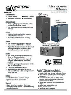
1 Air Handler bcs2 . APPLICATION Form No. ABCS2-100 (06/2011). 1 1/2 - 5 ton sizes Upflow and horizontal (counterflow capable with kits). Sequenced for demand management External access to heater circuit breakers INSTALLATION. 1 Piece design for easier installation Multiposition - Upflow/Horizontal Left/Right CABINET. Foil faced insulation Painted, heavy-gauge galvanized cabinet Filter rack built into every air Handler High-strength, UV- and heat-resistant plastic drain pan for corrosion resistance Microban antimicrobial built in to drain pan to resist mold and mildew growth and fouling of the drain 2% or less air leakage COMPONENTS.
2 Efficient PSC blower motors Standard transformer and blower relay Field-installed 5-20 kW electric heat kits with easy plug connections Built-in indoor time delay for increased efficiency Sleeves on distributor tubing to protect tubing ACCESSORIES. Counterflow kit Single point power kit WARRANTY. 10-year limited parts warranty available when applied with a system. See limited warranty document for details. Model Number Guide BC S 2 M 36 C 00 N A 1P - 1. Blower Coil Revision Code Single Piece Cabinet Metering Device 1P = Piston Orifice Series 4X = R410a TXV.
3 M = Multi-position (Upflow, Voltage - Horizontal Right or Left A = 208-230v/60Hz/1Ph Counterflow w/kit). Nominal Capacity Circuit Protection - 36 = 36,000 Btuh N = None Blower Motor - Heat Size C - Constant Speed 00 = kW Elec. kW Kits Available 18 - 5, , 10. 24 - 5, , 10. 30 - 5, , 10, 15. 36 - 5, , 10, 15. 37 - 5, , 10, 15. 42 - 4, , 10, 15. 48 - 5, , 10, 15, 20. 60 - 5, , 10, 15, 20. Physical Max. Refrigerant Elec. Heat Filter Size Connection (IDS) Florator Weight Model Volts/Hz/Phase Tranformer Size & Type Available (in.) Suction Liquid Piston Size (lbs.)
4 (kW) (in.) (in.). BCS2M18 208-230/60/1 10 40 VA, Class 2 16 X 20 3/4 3/8 .051 129. BCS2M24 208-230/60/1 10 40 VA, Class 2 16 X 20 3/4 3/8 .057 131. BCS2M30 208-230/60/1 15 40 VA, Class 2 18 X 20 7/8 3/8 .065 148. BCS2M36 208-230/60/1 15 40 VA, Class 2 18 X 20 7/8 3/8 .070 148. BCS2M37 208-230/60/1 15 40 VA, Class 2 18 X 25 7/8 3/8 .070 172. BCS2M42 208-230/60/1 15 40 VA, Class 2 18 X 25 7/8 3/8 .076 172. BCS2M48 208-230/60/1 20 40 VA, Class 2 18 X 25 7/8 3/8 .082 177. BCS2M60 208-230/60/1 20 40 VA, Class 2 18 X 25 7/8 3/8 .090 190. Dimensions (in.). Supply Duct Return Duct Air Opening Opening A B C.
5 Handler (in.) (in.) (in.) Depth Width Depth Width Size (in.) (in.) (in.) (in.). BCS2M18-24 46 3/4 22 18 1/2 17 16 1/2 20 1/4 16. BCS2M30-36 51 22 21 1/4 17 19 1/4 20 1/4 18 3/4. BCS2M37-48 54 26 21 1/4 21 19 1/4 24 1/4 18 3/4. BCS2M60 60 26 21 1/4 21 19 1/4 24 1/4 18 3/4. - Page 2 - Electrical Elec. Heating Cap. (2) (3) Total Amps per Circuit Circuit Breaker Blower Amps Total Unit Amps Blower Size kW Btuh 208v 240v Amps per Stage (1) 240v (1)) 240v 208v 240v 1 2 3 1 2 3 208 240 1 2. 18 & 24 (no heat) 0 0 - - - - - - 15 - 18 & 24 5 17,100 - - - - 30 - 18 & 24 25,600 - - - - 45 - 18 & 24 10 34,100 - - - - 60 - 30 (no heat) 0 0 - - - - - - 15 - 30 5 17,100 - - - - 30 - 30 25,600 - - - - 45 - 30 10 34,100 - - - - 60 - 30 15 51,200 - - 60 30.
6 36 & 37 (no heat) 0 0 - - - - - - 15 - 36 & 37 5 17,100 - - - - 30 - 36 & 37 25,600 - - - - 45 - 36 & 37 10 34,100 - - - - 60 - 36 & 37 15 51,200 - - 60 30. 42 (no heat) 0 0 - - - - - - 15 - 42 5 17,100 - - - - 30 - 42 25,600 - - - - 45 - 42 10 34,100 - - - - 60 - 42 15 51,200 - - 60 30. 48 & 60 (no heat) 0 0 - - - - - - 15 - 48 & 60 5 17,100 - - - - 30 - 48 & 60 25,600 - - - - 45 - 48 & 60 10 34,100 - - - - 60 - 48 & 60 15 51,200 - - 60 30. 48 & 60 20 68,300 - - 60 60. (1) For 208 volt use .751 correction factor for kW and Btuh (2) 15 and 20 kW (2 stage models) require 2 supply circuits (3) Circuit #1 includes blower motor amps - Page 3 - Blower Motor Size Blower Size CFM @ ESP - in.
7 Model Speed (hp) (in.) Low* (Red) 720 700 660 610 520. BCS2M18 1/4 10 x 6 Med (Blue) 1000 930 840 710 630. High (Black) 1040 960 870 780 660. Low (Red) 720 700 660 610 520. BCS2M24 1/4 10 x 6 Med* (Blue) 1000 930 840 710 630. High (Black) 1040 960 870 780 660. Low (Red) 930 920 890 840 740. BCS2M30 1/4 10 x 6 Med* (Blue) 1060 1040 1010 950 840. High (Black) 1290 1270 1210 1150 1040. Low* (Red) 1140 1120 1110 1080 1000. BCS2M36 1/3 11 x 8 Med (Blue) 1350 1350 1320 1260 1090. High (Black) 1490 1470 1420 1340 1250. Low* (Red) 1140 1120 1110 1080 1000. BCS2M37 1/3 11 x 8 Med (Blue) 1350 1350 1320 1260 1090.
8 High (Black) 1490 1470 1420 1340 1250. Low (Red) 1603 1542 1474 1407 1301. BCS2M42 1/2 11 x 8 Med* (Blue) 1707 1635 1567 1482 1373. High (Black) 1803 1749 1665 1545 1416. Low (Red) 1743 1700 1641 1565 1451. BCS2M48 1/2 11 x 8 Med* (Blue) 2158 1943 1826 1700 1581. High (Black) 2181 2112 1918 1771 1642. Low (Red) 1734 1712 1688 1644 1503. BCS2M60 1/2 11-1/2 x 9 Med* (Blue) 2080 2038 1971 1855 1717. High (Black) 2276 2184 2092 1958 1842. All data given while air Handler is operating with a wet DX coil and air filter installed. Speeds marked in italics with an asterisk* are the factory settings for both heating and cooling.
9 Cooling speeds should not be reduced below factory settings. Different speeds can be set for heating mode. Accessories Kit Number Description Used with 12W61 Counterflow Kit All BCSs LB62009C Single Point Power Kit All BCSs - Page 4 - Electric Heat Model Number Guide A EH BCC 05 N S A - 1. Accessory Revision Code Electric Heat A - 208-230V/60hz/1Ph Applicable Product Family Cabinet Size BC* - Air Handler Heat Size Circuit Protection 05 - 5 kW Electric N - None 07 - kW Electric C - Circuit Breaker 10 - 10 kW Electric 15 - 15 kW Electric 20 - 20 kW Electric Electric Heat Kits Kit Number Description Used on AEHBCC05 NSA-1 5 kW with Terminal Block bcs2 *18, 24, 30, 36, 37, 42, 48, 60.
10 AEHBCC05 CSA-1 5 kW with Circuit Breaker bcs2 *18, 24, 30, 36, 37, 42, 48, 60. AEHBCC07 NSA-1 kW with Terminal Block bcs2 *18, 24, 30, 36, 37, 42, 48, 60. AEHBCC07 CSA-1 kW with Circuit Breaker bcs2 *18, 24, 30, 36, 37, 42, 48, 60. AEHBCC10 NSA-1 10 kW with Terminal Block bcs2 *18, 24, 30, 36, 37, 42, 48, 60. AEHBCC10 CSA-1 10 kW with Circuit Breaker bcs2 *18, 24, 30, 36, 37, 42, 48, 60. AEHBCC15 CSA-1 15 kW with Circuit Breaker bcs2 *30, 36, 37, 42, 48, 60. AEHBCC20 CSA-1 20 kW with Circuit Breaker bcs2 *48, 60. - Page 5 - All specifications and illustrations subject to change without notice (800) 448-5872.


