Transcription of AIR OPERATED DOUBLE DIAPHRAGM PUMPDOUBLE DIAPHRAGM PUMP ...
1 HG-CF-998 Rev. D - 03/27/03 AIR OPERATED AIR OPERATED AIR OPERATED AIR OPERATED DOUBLE DIAPHRAGM PUMPDOUBLE DIAPHRAGM PUMPDOUBLE DIAPHRAGM PUMPDOUBLE DIAPHRAGM PUMP Full FlowFull FlowFull FlowFull Flow High Pressure SeriesHigh Pressure SeriesHigh Pressure SeriesHigh Pressure Series DATA SHEET, SERVICE & OPERATING MANUALDATA SHEET, SERVICE & OPERATING MANUALDATA SHEET, SERVICE & OPERATING MANUALDATA SHEET, SERVICE & OPERATING MANUAL Table of Contents Performance Curve 1 Dimensions 1 Engineering Data & Temperature limitations 2 Explanation of Pump Nomenclature 2 Principle of Pump Operation 3 Installation guide 3 Troubleshooting 4 Recycling 4 Important Safety Information 4 Warranty 5 Service 5 Air Valve Overhaul 5 Wet-side Overhaul 5 Parts List 6 Assembly Drawing 7 Technical Notes 8 Technical Notes 9 Service / Maintenance Log 10 HG-CF-998 Rev. D - 03/27/03 N25N25N25N25 AIR OPERATED AIR OPERATED AIR OPERATED AIR OPERATED DOUBLE DIAPHRAGM PUMPDOUBLE DIAPHRAGM PUMPDOUBLE DIAPHRAGM PUMPDOUBLE DIAPHRAGM PUMP Full Flow High Pressure SeriesFull Flow High Pressure SeriesFull Flow High Pressure SeriesFull Flow High Pressure Series DATA SHEET, SERVICE & OPERATING MANUALDATA SHEET, SERVICE & OPERATING MANUALDATA SHEET, SERVICE & OPERATING MANUALDATA SHEET, SERVICE & OPERATING MANUAL DISTRIBUTOR BLAGDON PUMPBLAGDON PUMPBLAGDON PUMPBLAGDON PUMP A Unit of IDEX Corporation IMPORTANT All business conducted subject to Blagdon Pump.
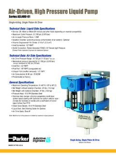
2 Terms and Conditions of Sale, available on request. Page 1 N25 Full Flow High Pressure Pump Performance Curve Performance based on water at ambient temperature 6017 ENTERPRISE DRIVE, EXPORT, PENNSYLVANIA 15632-8969, USA. TEL. : (1) 724-327-7867 FAX. : (1) 724-733-4786 Web Site : E-Mail : HG-CF-998 Rev. D - 03/27/03 FLUID CONNECTIONS CAPACITY MAX SOLIDS MAX DISCHARGE HEAD DISPLACEMENT/STROKE 1 NPT (F) 0 - 33 US Gallons/Minute (0 - 125 Liters/Minute) 1/8 (3 mm) 536 ft (163 Meters) US Gallons ( Liters) Materials Maximum Minimum Optimum Buna-n - General purpose, oil resistant. Shows good solvent, oil, water and hydraulic fluid resistance. Should not be used with highly polar solvents like acetone and MEK, ozone, chlorinated hydrocarbons and nitro hydrocarbons. 190oF 88oC -10oF -23oC 50o to 140oF 10o to 60oC EPDM - Shows very good water and chemical resistance. Has poor resistance to oils and solvents, but is fair on ketones and alcohols.
3 212oF 100oC -10oF -23oC 50o to 212oF 10o to 100oC Neoprene - All purpose. Resistant to vegetable oil. Generally not affected by moderate chemicals, fats greases and many oils and solvents. Generally attacked by strong oxidising acids, ketones, esters, nitro hydro carbons and chlorinated aromatic hydrocarbons. 170oF 77oC -10oF -23oC 50o to 130oF 10o to 54oC Santoprene - Injection moulded thermoplastic elastomer with no fabric layer. Long mechanical flex life. Excellent abrasion resistance. 212oF 100oC -10oF -23oC 50o to 212oF 10o to 100oC Virgin PTFE - Chemically inert, virtually impervious. Very few chemicals are known to react chemically with PTFE : molten alkali metals, turbulent liquid or gaseous fluorine and a few fluoro-chemicals such as chlorine trifluoride or oxygen difluoride which readily liberate free fluorine at elevated temperatures. 212oF 100oC -35oF -37oC 50o to 212oF 10o to 100oC Viton - Shows good resistance to a wide range of oils and solvents : especially all alphatic, aromatic and halogenated hydrocarbons, acids, animal and vegetable oils.
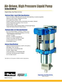
4 Hot water or aqueous solutions(over 700F) will attack Viton . 212oF 100oC +32oF 0oC 75o to 212oF 24o to 100oC Polypropylene 150oF 65oC -40oF -40oC Operating Temperatures Page 2 TYPICAL CODE = N25. 01. A A. B 3. N N S DIAPHRAGMS T : PTFE N : NEOPRENE CHECK VALVES T : PTFE N : NEOPRENE VALVE SEATS S : STAINLESS STEEL WETTED COMPONENTS A : ALUMINUM S : STAINLESS STEEL DESIGN LEVEL NON - WETTED COMPONENTS A : ALUMINUM CHECK VALVE B : BALL W : WEIGHTED BALL MODEL DESIGNATION TECHNICAL DATA METALLIC SERIES - FULL FLOW 2:1 N25 Maximum Delivery: 33 gpm Installation: Surface mounted Max. Working Pressure: 116 psi Accessories Included: Exhaust air Silencer Max. Solid Particle Size: 1/4 Shipping Weights: Air Inlet: 3/8 NPT (F) Aluminum 56 lb Temperature Limits: Determined by Elastomers Stainless Steel / Aluminum 76 lb Suction Lift (Dry): 20 Shipping Dimensions: 18 x 19 x 12 1/4 Suction Lift (Wet): 25 Fluid Inlet/Outlet: 1 NPT (F) MODEL - N25 HG-CF-998 Rev.
5 D - 03/27/03 Page 3 PRINCIPLE OF PUMP OPERATION This ball type check valve pump is powered by compressed air and is a 2:1 ratio design. The inner side of one DIAPHRAGM chamber is alter-nately pressurised while simultaneously ex-hausting the other inner chamber. This causes the diaphragms, which are connected by a com-mon rod secured by plates to the centers of the diaphragms, to move in a reciprocating action. (As one DIAPHRAGM performs a discharge stroke the other DIAPHRAGM is pulled to perform the suction stroke in the opposite chamber.) Air pressure is applied over the entire inner surface of the DIAPHRAGM while liquid is discharged from the opposite side of the DIAPHRAGM . The DIAPHRAGM operates in a balanced condition during the discharge stroke which allows the pump to be OPERATED at discharge heads of over 500 feet (152 meters) of water.
6 For maximum DIAPHRAGM life, keep the pump as close to the liquid being pumped as possible. Positive suction head in excess of 10 feet of liquid ( meters) may require a back pres-sure regulating device to maximize DIAPHRAGM life. Alternate pressurising and exhausting of the DIAPHRAGM chamber is performed by an exter-nally mounted, pilot OPERATED , 2 way type distibution valve. When the spool shifts to one end of the valve block body, inlet pressure is applied to one chamber and the other DIAPHRAGM chamber exhausts. When the spool shifts to the opposite end of the valve body, the pressure to the chambers is reversed. This alternating move-ment of the spool inside the valve body is con-trolled by a pilot air pressure signal held against the DIAPHRAGM connecting rod, between seals in the DIAPHRAGM shaft bushes.
7 This signal is re-leased, triggering the movement of the spool, when pilot holes in the DIAPHRAGM connecting rod align with the held pilot signal, sending the signal to exhaust, which in-turn causes a pres-sure imbalance around the spool, sending it to the opposite end of the valve body. This simuta-neously sends inlet pressure to the opposite chamber. The chambers are connected with manifolds with a suction and discharge check valve for each chamber, maintaining flow in one direction through the pump. The 2:1 ratio discharge pres-sure is generated by simultaneously delivering air inlet pressure to alternate sides of a central air DIAPHRAGM , the chambers either side of this central DIAPHRAGM are pressurised and exhausted in conjunction with the main DIAPHRAGM cham-bers. INSTALLATION The typical installation shown in FIG.
8 1 is only a guide to selecting and installing system components. Your installation will depend on the type of fluid being pumped and your application needs. To reduce the risk of serious bodily injury and damage to property, never use fluids in this pump which are not compatible with the wetted components. Contact your local distributor or the manufacturer for system design assistance & compatibility if necessary. Mount the pump in an upright position. Failure to ensure an upright position may result in loss of or poor priming characteristics. Ensure the pump is securely mounted to avoid movement and possible risk of bodily injury. PRESSURE The pump delivers DOUBLE the pressure at the discharge outlet as the air pressure applied at the air inlet. NOTE: Pressure Regulator (H) should be installed where air supply could exceed 125 psi.
9 SAFETY Your BLAGDON PUMP is a high performance unit capable of achieving high outputs at high efficiencies. However, as is common with pneumatic equipment, the pump efficiencies is reliant upon the air being clean, dry and filtered. Failure to comply with these requirements may lead to loss of performance and reduced component life and in extreme cases, permanent damage to the pump. To avoid leaks, ensure that all fluid connections are tight. The use of PTFE thread tape correctly applied should be used to ensure 100% leakproof connections. Failure to ensure 100% sealability of the suction connection could adversely affect suction performance. If you are pumping hazardous fluids, or operating the pump in an enclosed area, it is essential that the exhaust from the pump is piped away to a safe location.
10 When pumping hazardous fluids the above instructions must be adhered to in order to ensure safe operating procedures. (Under certain operating conditions the failure of internal components can lead to the pumped fluid being exhausted via the pump exhaust outlet). WARNING NEVER place your hands over or near the pump suction inlet. Powerful suction could cause serious bodily injury. FLUSH THE PUMP This pump was tested with water containing an oil-based rust inhibitor. If this solution could contaminate or react with the fluid you are pumping, flush the pump thoroughly with a solvent/detergent to clean internal components. The solvent/detergent must be compatible with the pump materials of construction. Care should be taken to flush the pump each time it is disassembled for maintenance or repair.