Transcription of Air Operated Grease Ratio Pumps 50:1 GP1, GP2, GP3
1 1 INSTRUCTION MANUALS1230, Rev DAir Operated Grease Ratio Pumps 50:1GP1, GP2, GP3 Congratulations on purchase of this World Class Air Operated Grease Ratio Pump ! World-class Industrial High Pressure Grease pump with guaranteed performance & hassle free operation Pump dispenses Grease at pressures upto 50 times the Air inlet pressure Designed to work in tough conditions- Ideal for use in Industry, workshop, farm, construction or as part of the Mobile Grease system All metal construction, fully CNC machined with hardened wear resistant moving parts Reciprocating piston Operated (63 mm) dia.
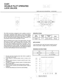
2 Air Motor Fitted with strainer at suction tube inlet for clean Grease to the bearing Supplied in two choices :- - Pump Only - Pump with Drum Cover, Rubber Lined Follower Plate, High Pressure Grease Hose, Z swivel & Professional Grease Control ValveGrease Control ValveAir Motor AssemblyZ SwivelDrum CoverHigh Pressure Rubber HoseCover ScrewsSuction TubeFollower PlateNozzle Page CONSTITUENTS ..PUMP CONSTRUCTION ..WORKING OF PUMP ..INSTALLATION ..PUMP OPERATION ..MAINTENANCE & REPAIR ..EXPLODED VIEW.
3 PARTS LIST ..TROUBLESHOOTING ..REPLACEMENT & SERVICE PARTS PROGRAM FOR Grease Ratio PUMP ..SPECIFICATIONS ..WARNINGS ..334567-111213-141516-181919 Pumping Section Kit Replacement .. Drive Section Kit Replacement.. Replacement Parts Program .. Service Parts Program (Pumping Section Kit - KIT/BTM/RP-G) .. Service Parts Program (Drive Section Kit - KIT/TP/RP-G) ..1617187-89-113 PUMP CONSTITUENTSPUMP CONSTRUCTIOND rive SectionPumping Section15243 The pump is made up of two sections as given below :- Drive section :- It consists of an Air Motor Assembly driven by compressed air.
4 The piston diameter of the air motor is / 63 mm. The motor consists of an air cylinder with piston and one reciprocal valve with a nylon slider. The valve directs the compressed air alternately to the top or bottom of the piston, thus producing a reciprocating motion of the piston rod. Pumping Section :- It consists of a pump in which a piston lifts the Grease through Non Return Valves by reciprocating inside the pump cylinder. The Grease is discharged with pressure (from the outlet located at bottom of Air Motor) into the delivery MOTOR of these Pumps starts automatically when the Grease Control Valve is opened.
5 When the valve is closed, Air Motor builds up a back-pressure and stops operating the pumping Ratio of the pump states the Ratio of the output Grease pressure to the incoming air pressure. When the pressure Ratio is 50:1, we achieve an output Grease pressure up to 7500 PSI (500 BAR) when the incoming air pressure is 150 PSI (10 BAR ).1. Grease Pump Assembly2. Drum Cover with Thumb Screws3. Rubber Lined Follower Plate4. High pressure Rubber Hose 5. Professional Grease Control Valve with Z Swivel Fig. 2 Fig. 34 The air motor repeats Upstroke & Downstroke in continuous cycle to produce a reciprocating motion, driven by compressed air.
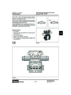
6 This motion is transferred via a connecting rod to the piston in the Pumping Section. During every upstroke, non return valves (with spring & ball check) get opened & the piston lifts the Grease . During every downstroke, non return valves get closed & the piston discharges Grease from the outlet valve. Closing the Grease Control Valve shuts off the air motor & pump stops dispensing OF PUMPUPSTROKEDOWNSTROKEABCDGHJIUPSTROKE - When Grease Control Valve is opened, compressed air enters at arrow A and passes through passage B to the underside of the Piston C, driving the Piston C and Piston Rod D upwards.
7 The air above the Piston is evacuated through passage E, past the Slider Valve F and out at arrow G. The Piston approaches top dead centre and Piston Rod D makes contact with the Slider Rod H. Now the Slider Rod H starts moving up with the Piston Rod D. DOWNSTROKE -The incoming air is now led via passage E to the upper side of Piston C, driving it and the Piston Rod D downwards. The air under the Piston C is evacuated through passage B, past the Slider Valve F and out at arrow G. The Piston approaches bottom dead centre and Piston rod D makes contact with the Slider Rod H.
8 When Slider Rod H passes its centre position, the Pusher Spring I and Pusher Button J snap it over to its lower 4 Fig. 55 INSTALLATION1. Fill the drum with Grease leaving empty space of about 2 from the top rim. Shake the drum after it is filled to remove air pockets. Place the follower plate in the Grease drum with the lift handle facing upwards. Push the follower plate down, until some Grease is forced through the centre hole on the plate. 2. Place the drum cover on the drum. Lift the pump assembly & slide the suction tube through the drum cover & centre hole in the follower plate.
9 3. Push the pump assembly down till the bottom of the pump touches the base of the drum. Adjust the drum cover and tighten it with the thumb screws provided along with the drum FRL (Filter-Regulator-Lubricator) unit must be used in the Air supply, before it is connected to the pump. Set the regulator to 6 BAR (90 PSI) or any required inlet pressure, but never more than 150 PSI (10 BAR) or less than 30 PSI (2 BAR).4. Tighten the drum cover with the pump suction tube with the help of thumb Use a wrench to tighten high pressure hose to the pump Use a wrench to tighten the other end of the hose to Z Swivel of Grease control valve.
10 Tighten the outlet extension & coupler to the control valve outlet. Use thread sealant on all connections to ensure leak-proof With the air supply turned off, connect the Air line into the air inlet on the pump. NOTEAir LineZ SwivelThumb ScrewThumb ScrewsExtension & CouplerHoseLift Handle61. Partially open the on/off air valve (It helps in creating initial vacuum when filling a totally dry pump). Pump will start operating automatically until it gets primed. Pump is said to be Primed when Grease is available at the pump outlet, making the pump ready to use.