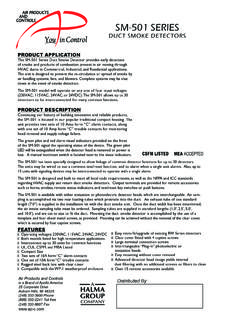
Transcription of AIR PRODUCTS AND CONTROLS INC. - AP-C
1 YouYou in control in ControlANDANDAIR PRODUCTSAIR PRODUCTSCONTROLSCONTROLSAIR PRODUCTS AND CONTROLS INSTRUCTIONS FOR DUCT SMOKE DETECTORREMOTE ACCESSORIES25 Corporate Drive Auburn Hills, MI 48326 USA US Toll Free Phone Fax *NOTE:For proper installation, testing, operation and maintenance of a duct smoke detector, please refer to the detector installation guide. Thefollowing wiring diagrams are applicable only to compatible, current limited, UL Listed remote accessories from Air PRODUCTS and CONTROLS .
2 Use ofany other devices may result in damage to the duct smoke detector, potential injury, and will void any applicable Series Duct Smoke Detectors*NOTE:For remote accessories with a Trouble LED (yellow), a jumper wire must be placed between Terminals 20 and 15. The Trouble LED willilluminate when the detector cover is removed, or if the smoke detector head is removed and the cover replaced. Trouble contacts CANNOT beconnected to a Fire Alarm control Panel when using this option without the use of a slave relay.
3 *NOTE:If duct smoke detectors are interconnected for common functions, please refer to unit installation guide for proper connection of remotealarm REENPIL O TLEDBL ACKRED219 PILOTBL ACKBL ACKKEY O RPUSH BUTTO N TEST / RESET SWITCH120 TEST / RESETTROUBLEREDBL ACKYEL L O WTROUBLELED4192015 JUMPERSM-501 Series Duct Smoke Detectors*NOTE:For remote accessories with a Trouble LED (yellow), a jumper wire must be placed between Terminals 14 and 18. The Trouble LED willilluminate when the smoke detector head is removed.
4 Trouble contacts CANNOTbe connected to a Fire Alarm control Panel when using this optionwithout the use of a slave relay.*NOTE:If duct smoke detectors are interconnected for common functions, please refer to unit installation guide for proper connection of remotealarm ARMLEDREDBL ACKSTRO BEAND/O RHO RN1719 ALARMG REENPIL O TLEDBL ACKRED2119 PILOTBL ACKBL ACKKEY O RPUSH BUTTO N TEST / RESET SWITCH2120 TEST / RESETTROUBLEREDBL ACKYEL L O WTROUBLELED13191418 JUMPERINST APD0127 D080430A COPY OF THESE INSTRUCTIONS SHOULD BE LEFT WITH THE EQUIPMENT UNTIL INSTALLATION BY ALL TRADESIS FULLY FINAL INSPECTION.
5 A COPY SHOULD BE LEFT WITH THE ACCESSORIES FOR USE WITH AIR PRODUCTS DUCT SMOKE DETECTORSREMOTE ACCESSORIESMS-RARemote AlarmMS-RA/RRemote Alarm, push button Test/Reset SwitchMS-RA/P/RRemote Alarm, Pilot, push-button Test/Reset SwitchMS-KA/RRemote Alarm, key-operated Test/SwitchMS-KA/P/RRemote Alarm, Pilot, key-operated Test/Reset SwitchMS-RA/PRemote Alarm, PilotMS-RHRemote Alarm HornMS-RH/KA/P/R Remote Alarm, Pilot, Horn, key-operated Test/Reset SwitchMS-RH/P/ARemote Alarm, Pilot, HornMS-RH/KA/P/A/TRemote Alarm, Trouble, Pilot, Horn, key-operated Test/Reset SwitchMS-RA/P/TRemote Pilot, TroubleMS-RA/FT/PRemote Pilot, Trouble, push-button Test/Reset SwitchMS-KA/P/R/TRemote Pilot, Trouble, key-operated Test/Reset SwitchMS-RDRemote AlarmMS-F/TRemote TroubleSHP24-1575 RHorn/Strobe, red housing, clear coverSHP24-1575 OHorn/Strobe, white housing, opaque coverSHP24-1575W Horn/Strobe, white housing.
6 Clear coverSMOKE TEST GASTG-1000 Solo Aerosol Test Gas with Spray NozzleTG-2000 Solo Aerosol Test Gas with Nozzle for SL- Series Test PortSAMPLING TUBES (RW- AND SM- SERIES)NOTCHED SAMPLING TUBES (SL- SERIES) duct widths of 6 TO duct widths of 6 TO duct widths of TO duct widths of TO duct widths of TO duct widths of TO duct widths of TO duct widths of TO WEATHERPROOF ENCLOSURESWP-1 Weatherproof Enclosure for RW- and SM- Series DetectorsWP-2000 Weatherproof Enclosure for SL- Series DetectorsPOWER SUPPLIEST-PB 202-124 VAC @ Class I Power SupplyT-PB 202-024 VAC @ Class I Power SupplyT-PB 303-124 VAC @ Class II Power SupplyT-PB 303-024 VAC @ Class II
7 Power SupplyNOTICE:The information contained in this document is the most current available at the time of shipment of accompanying product , and is subject to change without notice. Future references should always be madeto the most current revision of this document. The information contained in all this document should be considered before installing or using the product . Any example applications shown are subject to the most cur-rent enforced local/national codes, standards, approvals, certifications, and/or the authority having jurisdiction.
8 All of these resources, as well as the specific manufacturer of any shown or mentioned related equipment,should be consulted prior to any implementation. For further information or assistance concerning this product , contact Air PRODUCTS and CONTROLS Inc. Air PRODUCTS and CONTROLS Inc. reserves the right to change any andall documentation without notice. Air PRODUCTS and CONTROLS Inc. 2007MS SERIES REMOTE ACCESSORIESP ower Requirements:Alarm LED15mA @ 24 VDCT rouble LED15mA @ 24 VDCP ilot LED15mA @ 24 VDCA larm Horn20mA @ 24 VDCS ound Pressure:78db @ 10 ftDimensions:Single Gang4 ( )H x 2 ( )WDouble Gang4 ( )H x 4 ( )W Wiring:LEDs/Horn6 24 AWG PigtailsSwitches6 22 AWG PigtailsApprovals:UL Listed for use with Air PRODUCTS and CONTROLS duct smoke detectors including all RW- Series, SM- Series and SL- Series duct smoke detectorsUL 7300-1004.
9 107 MEA 73-92-E ARMLEDREDBL ACKSTRO BEAND/O RHO RN1219 ALARMREDAL ARMLEDREDBL ACKSTRO BEAND/O RHO RN1119 ALARMBUZZERBUZZERDETECTOR PCB HAS NOWHITE STRIPE ON LEFT EDGEPCB HAS WHITE STRIPEON LEFT EDGEHS-100 Series Duct Smoke Detectors*NOTE:If duct smoke detectors are interconnected for common functions, please refer to unit installation guide for proper connection of remotealarm ARMLEDREDBL ACKSTRO BEAND/O RHO RN1312 ALARMG REENPIL O TLEDBL ACKRED1412 PILOTBL ACKBL ACKKEY O RPUSH BUTTO N TEST / RESET SWITCH157 TEST / RESETTROUBLEREDBL ACKYEL L O WTROUBLELED1112 RWJ Series Duct Smoke DetectorsRWF Series Duct Smoke DetectorsRWX Series Duct Smoke DetectorsRWL Series Duct Smoke DetectorsRWH Series Duct Smoke Detectors*NOTE.
10 For RWJ Seriesduct smoke detectors, no jumper is required for remote accessory Trouble conenctions. A Trouble LED (yellow) con-nected to Terminals 13 and 20 will illuminate when the smoke detector is removed. If the trouble contacts of the RWJ Series detector are being usedfor other switching applications, or for connection to a Fire Alarm control Panel, the on-board RWJ option jumper must be removed (cut). Failure toremove the RWJ option jumper could result in damage to the Fire Alarm control Panel or other connected equipment.


