Transcription of Air Suspension Systems Basic Training 15 - WABCO
1 12 IntroductionIf we look at the different Suspension Systems used in motor vehiclestoday, the most apparent difference between them is that they are eithermechanical or air Suspension types are, of course, incapable of meeting all technicalrequirements. If they are, however, directly compared, it soon becomesapparent that air Suspension offers major benefits compared withmechanical Suspension a result air Suspension Systems are used to an increasing extent incommercial of Air Suspension Systems1. By changing the bellows pressure, depending on the load carried onthe vehicle, the distance between the road surface and the vehicle ssuperstructure addresses the same level. This means that theboarding or loading height, and the headlight settings, Spring comfort remains almost unchanged across the whole of theloading range; again this is achieved by changing the bellowspressure. The passenger on a motor coach will always perceive thesame pleasant type of oscillations.
2 Sensitive loads can thus becarried without being severely damaged. The well-known jumping of an unladen or partially laden trailer no longer occurs if an airsuspension system is The stability of the steering system and the transfer of the brakingforces are improved since all wheels always have good adhesion tothe road The pressure in the air bellows, depending on the load the vehiclecarries, is ideal for use in controlling automatic In the area of control for interchangeable platforms, air suspensionsystems are an excellent basis for cost-effective loading andunloading of The kneeling effect often required for routine buses can easily beachieved by venting the nearside air Suspension SystemsBasic Training152 Air Suspension BellowsBasic Training15 PurposeDepending on the levelling valve s control, the air Suspension bellowsare designed to take up the required pressure in the bellows volume.
3 Depending on the load carried on the Suspension bellows are used as elastic constructional elementsbetween the axle and the vehicle s superstructure. Since its internalfriction is less than that of mechanical Suspension Systems , the air-sprung vehicle has to have shock-absorbers typesToday the following variants are mainly used:Twin Concertina BellowsTwin concertina bellows show a favourable ratio of height versus springtravel, i. e. this type of bellows permits the lowest installation beaded heels around the bellows openings are held by metallicbead rings which are screwed against supporting consoles or causes part of the bellows heels to be deformed, thereby achievinga sealing Tube BellowsRolling tube bellows achieve an excellent cushioning effect and offerexceptionally good lateral movement. For this reason they areparticularly suitable for use in buses and passenger cars but are alsoused on lorries and the course of their cushioning action, these bellows roll on a cylindricalor similar piston whose shape essentially effects the cushioningcharacteristic.
4 This allows the natural frequency to be varied and thebest possible Suspension for the vehicle to be achieved. For thispurpose, rolling tube bellows require no additional volume. The airvolume in the piston can also be used for bellows are fairly easy to install and to seal. The bellows heelsare pushed onto conical fittings and assume their intended positionwhen connected to the air maintenance is required beyond the checks required by Suspension bellows merely need to be checked for any leakage, andfor mechanical valves, also called air Suspension valves, are used to controlthe Suspension in air-sprung vehicles. Their purpose is the sensitivelygraded control of the compressed air for the air Suspension bellows asa ratio of the vehicle s types464 002 .. 0 Levelling valves with single or double-stage characteristic curve. Thedamping nozzles for energy delivery to the air Suspension bellows varieswith the respective variants ( mm resp. 3 mm).
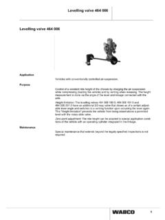
5 They use either a flatlever with a ball joint, or a linkage with a rubber transmitting 006 .. 0 Levelling Valve 464 006 .. 0 Devives (in dual level characteristic) replace the designs 464 002 .. andhave a nominal width of 3 are following design types:Levelling Valve 464 006 00. 0 (without height limitation)The device is available in different variants (with or without lever ). They use either a flat lever with a ball joint, or a linkage with a rubbertransmitting Valve with height limitation 464 006 100 variant has an additional 3/2 way valve which closes, from a specialadjustable lever angle up, the pressure supply to the air bellows and turninto a venting position when the lever further is this Height Limitation a lift up of the vehicle with the rotaryslide valve over the admissible level is prevented. This integratedsolution makes the former necessary seperate shutoff valve for strokelimitation ValvesBasic Training154 Levelling ValvesBasic Training15 Operation of Levelling Valve 464 002a.
6 Pressurizing PositionIf the vehicle is pressureless, its superstructure rests on the rubberbuffers of the chassis. The levelling valve has thus been reversed via thelinkage (10), causing the valve (5) on the inlet side to open. Thecompressed air from the air Suspension s auxiliary air reservoir nowenters at port (1), opening the check valve (4), and flows through theopen valve (5) past the tappet (6) into chamber (a). Through thecalibrated nozzle holes (b), the compressed air flows to ports (21 and22) and from there to the air Suspension bellows. As the vehicle ssuperstructure rises, it simultaneously acts on the eccentric pin (8) viathe linkage (10). This causes the guide (7), together with the tappet (6),to be pulled downwards. When the level for loading the vehicle, or forboarding passengers, has been reached, the inlet side of the valve (5)closes, and the process of pressurizing is finished. Because of thegroove-shaped top of the tappet (6), the nozzle holes (6) are When Axles OscillateAny axle oscillations, caused by uneven road surfaces as a ratio of thevehicle s speed, are transferred directly to the levelling valve.
7 Althoughthis may cause the valve (5) to open, the air consumption is kept to aminimum because the nozzle holes (b) are covered by the tappet (6).c. When LoadingWhen the vehicle is being loaded, the existing bellows pressure is nolonger sufficient to keep the superstructure at its level. It movesdownwards, causing the tappet (6) to reverse via the guide (7). The inletside of the valve (5) opens, and the tappet (6) releases the nozzle holes(b), allowing compressed air at a higher pressure to flow to theconnected air Suspension bellows. As described under a above, thelevelling valve reverses as the vehicle s superstructure is When UnloadingWhen the vehicle is unloaded, the levelling valve is controlled in reverseorder. Its superstructure rises, moving the guide (7), together with thetappet (6), downwards via the linkage (10). As the tappet (6) is raised offthe valve (5), the nozzle holes (b) are released and the air suspensionbellows are connected with the levelling valve s exhaust (3).
8 As thepressure in the air Suspension bellows is reduced, the vehicle ssuperstructure drops and the levelling valve is set back to its originalposition in which its air intake and its exhaust are the air Suspension bellows have the required pressure, thelevelling valve is only checked for any leakages, and for mechanicalwear of the NoteThe factory setting of the levelling valve should not be changed in termsof its empty stroke via the adjusting screw (9), or the centering plate sPhillips screws, since this would neutralize its Basic for Testing and Installation52, 6712414221414212, 6124381885743822211 Air- Suspension bellowsSupplyof theService Braking SystemLoad sensing valveLoad sensing valveLevelling ValvesBasic Training156 Adjustment of Levelling ValveBasic Training15 After mounting the air levelling valve, the lever length isadjusted following the vehicle manufacturer sinstructions. For adjusting the valve at the vehicle it isdecisive which total spring travel the axle the air Suspension bellows are pressureless, thevehicle s superstructure rests on the rubber buffers of thechassis.
9 As the bellows are pressurized, thesuperstructure is the air Suspension bellows unladen level (levelfor loading or for mounting passengers) has beenreached, the lever on the valve is moved to its neutralposition. To facilitate the installation and adjusting oflever and connecting linkage the levelling valve shaft canbe fixed by plugging a parallel pin of 3 mm in the the vehicle is at a normal level, the connecting linkagecan be installed. The linkage has to be aligned vertically. The space A between the fulcrum on the levelling valvelever and the fulcrum on the angle bracket should not beless than 150 mm. The linking 433 401 003 0 has to beordered relation lever length L / rod length A should be the closing angle of max. 45 is not exceeded. The leverlength L should be 175 to 295 mm (following theinstructions of the vehicle or Achsherstellers) betragen. Ifa shorter lever has to be used, a higher air consumptionof the levelling valve has to be on the fitting positon various cranks of thelever are possible.
10 By accordingly fixing or turning thelever for 180 the valve can be optionally operated fromright or left. Depending on the final installation positon -vertical or horizontal - the lever is to be placed throughone of the two bores in the operating shaft which arediplaced to each other for 90 .Variant .. 100 0 is adjusted to a closing angle of 30 2 by plant. The pilot pressure is 15 - 45 bar. A closingangle of 15 is not permissible, otherwise the cross-section will reduce itself and this can lead to adjustment of the closing angle the rubber plugunderneath the 3/2-Directional Control Valve has to beremoved to adjust the adjusting screw with a Torx T30screwdriver: - Counterclockwise means a reduction of the closingangle, clockwise means an increasing. - A rotation = approx. 10 changing of the angleAfter the vehicle has been lowered to its buffers with thehelp of a rotary valve the height of the chassis has to bemeasured.