Transcription of Air Terminal Unit (Mark Air Valves) - Rosemex, …
1 VENTILATION. 97. 7. Rosemex Products AIR. Terminal . unit . mark air valves . 2. mark air valves CV, VV & VVS. INDEX VALVE FEATURES The VVS valve will provide accurate Applications .. 3 Compact, lightweight permits flexibili- air volume control in all low or high Operation .. 4 ty in job applications and reduced pressure applications and maintain Selection .. 5 installation costs, easily located for thermostatic settings independent of Key criteria re selection and convenient access. system pressure variations. Sizing of mark air valves .
2 6. Simplicity of design and rugged com- Section 1: Valve models .. 6. ponents assure consistent and main- TYPICAL APPLICATIONS. Section 2: Control modes .. 6. tenance free performance Field 1. Interior zones require cooling year Section 3: System static pressure 6. proven. round. Load variations caused main- Section 4: CFM range .. 6. Section 5: Control sensitivity .. 7 Factory calibrated, no costly field bal- ly by shifting occupancy can be effi- Section 6: Capacity safety margin . 7 ancing. Future additions to system ciently handled with MA-VV valves Section 7: Acoustic considerations.
3 7 will not require rebalancing of original supplying multiple outlet boxes and Section 8: Special applications .. 7 valves . light troffer diffusers. Section 9: Selection charts .. 7 External adjustment and graduated 2. Exterior zones can use MA-VV. Selection chart I .. 8 dial: no special tools or flow measur- valves with reheat coils. Heating Selection chart II .. 9 ing devices required for volume costs are reduced since thermostat Mark Air valve acoustic treatment change. controls the air valve and water and system design .. 10 Sturdy cylindrical aluminum housing valve in sequence.
4 When room tem- mark air valves and typical for slip-in connection, fewer transi- perature is too low, MA-VV valve is distribution systems .. 11 tions. throttled to minimum. Only if addi- Ducted sound MA-CV and VV .. 12 tional heating is required will the hot Radiated sound CV and VV .. 13 Corrosion resistant construction of water valve open. Sound power levels .. 14 aluminum and stainless steel. Ducted and radiated NC levels .. 15 CV and VV Selection of 5 sizes up 3. MA-CV valves can also be used to Definitions .. 20 to 1750 CFM per valve (H).
5 Eliminate the critical balancing of pri- Linearisation output module (LOM) 21 mary air serving induction units. VVS Selection of 4 sizes up to 1500. Specification guide .. 22 Specified air volume is maintained CFM per valve (H). year round. High, Medium and Low pressure ranges. 4. Several recent applications have taken advantage of the compact size of mark air valves in using an APPLICATION all air system. The skin of the build- mark air valves are used in sup- ing is handled by MA-VV warm air ply or exhaust systems, for constant valves supplying more or less heat or variable volume, with or without at the window.
6 Variable volume cool reheat, in single or duel duct sys- air is supplied year round at the ceil- CONCEPT. tems. ing by MA-VV valves . Both valves CONSTANT VOLUME SYSTEMS: are controlled by a single thermostat mark air valves represent a so that as one closes the other unique and radically different techni- MA-CV MARK AIR VALVE. opens. cal approach to the challenge of con- Assures specified air flow regardless trolling ducted air volumes. of pressure variations. Completely 5. Either low or high pressure constant mark air valves provide accurate air self contained.
7 Volume MA-CV valves are recom- volume control in all low or high pres- VARIABLE VOLUME SYSTEM: mended for use with absolute filters. sure applications and maintain MA-VV MARK AIR VALVE. As filter resistance increases, valve required air volume independent of resistance decreases to maintain With pneumatic or electronic opera- system pressure variations. This is specified air volume. Typical appli- tor, offers true proportional control achieved by having a movable cone cations are hospital operating when connected to a zone thermo- inside a round venturi shaped hous- rooms, laboratories and clean stat.
8 Maintains all thermostatic set- ing. The spring controlled cone re- rooms. tings regardless of pressure changes adjust to pressure variation before or before or after the valve. 6. Low pressure variable volume MA- after the valve. No external flow con- VV valves are ideal for exhaust or SHUT-OFF VARIABLE VOLUME. trol device is required. return systems. As illustrated a SYSTEM: MA-VVS MARK AIR. VALVE selector switch, located at the fume hood, sets the valve for minimum or With the addition of the shut-off fea- maximum volume. Can also be used ture, valves may be used where to control hood air volume in multiple 100% closure is required, may be fume hood applications.
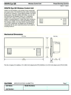
9 Used in conjunction with a smoke detector for supply and exhaust sys- 7. mark air valves are ideal for tems, and for duel duct applications. retro-fit applications. 3. APPLICATIONS. Regardless of the type of system, the Mark Air valve assures specified air volume and minimizes balancing. FIGURE 1. For further details and special applications contact Rosemex engineering. 4. OPERATION. FIGURE 2. MODEL MA-CV VALVE. AUTOMATICALLY MAINTAINS A Air volume is kept constant at a speci- increasing the resistance so as to main- CONSTANT AIR VOLUME CORRES- fied flow by locking the control rod in tain constant volume.
10 With a decrease PONDING TO A MANUALLY SET reference to the calibration dial. The in pressure, the spring pushes the cone POSITION, INDEPENDENT OF PRES- cone is free to move in response to fluc- out of the throat, reducing the resis- SURE CHANGES. tuations in pressure. An increase in tance. For an other air volume selec- pressure ahead or after the valve push- tion, the control rod is simply set to a es the cone deeper into the venturi, new dial position. FIGURE 3. L. MODEL MA-VV VALVE. AUTOMATICALLY MAINTAINS A By mounting a pneumatic or electronic mum limits.