Transcription of Aircraft Gas Turbine Blade and Vane Repair - tms.org
1 Aircraft GAS Turbine Blade AND VANE Repair . Antony and Goward Turbine Components Corporation Branford, Connecticut 06405. Abstract The high replacement costs of Aircraft gas Turbine blades and vanes have created a fast-growing, highly-specialized segment of the Aircraft Repair industry. The economic rationale for Repair in lieu of replacement is prima facie. The metallurgical rationale is less certain, but satisfactory flight performance over the past twenty-five years at least attests to the technical adequacy of Blade and vane repairs. Blade repairs, other than re-coating, generally consist of weld overlays on low-stress Blade tip or tip shroud locations. On average, high-pressure Turbine blades undergo two Repair cycles before replacement. Low-pressure Turbine blades similarly require Repair but are replaced less frequently. Dimensional restoration of a subtly distorted component to demanding original equipment standards is a real engineering challenge.
2 Coating technology is an equally sophisticated aspect of Blade Repair . Vane repairs are more avant-garde ranging from platform dimensional restoration to complete airfoil replacement. Vane airfoil crack Repair is commonplace and involves a multiplicity of processes many of which are still maturing. The future of Blade and vane Repair , like the past, will be determined by replacement part pricing. The technical considerations will remain as they are but Repair will probably become less labor-intensive as automation becomes more feasible. Superalloys 1988. Edited by S. Reichman, Duhl, G. Maurer, S. Antolovich and C. Lund The Metallurgical Society, 1988. 745. Introduction Gas Turbine blades experience dimensional and metallurgical degradation during engine operation. Dimensional degradation derives from wear, nicks, dents, hot corrosion and, in the case of coated blades, stripping and re- coating as in Repair . Metallurgical degradation derives from fatigue and high-temperature creep.
3 Some degradation, depending on location and extent, is ammenable to " Repair "; the definition of Repair being rather broad. That is, only very rarely does a Repair provide a part that is equivalent in all respects to a new part. This is not to say that the Repair is not safe and cost effective. For example, dimensional restoration of a Blade tip by welding provides a part which is functionally satisfactory even though the weld area does not have properties equivalent to the parent material. Repair procedures and limits are established by the engine manufacturer and are interpreted and applied by the engine operator and/or Repair facility. This paper will review some statistics relating the needs for Repair or re- placement, coating technology related to Blade and vane Repair , and the types of repairs that are commonly applied to contemporary hardware. Finally, some predictions on the future of Repair technology will be attempted.
4 Some Statistics on Blade and Vane Repairs Approximately twelve percent of the blades in a typical, moderately aged commercial engine are classified as non-repairable during routine overhaul. Typical Blade rejection rates, by stage, are summarized in Table I. Table I. Typical Blade Repair Rejection Rates Stage Rejection Rate 1 30%. 2 7%. 3 6%. 4 3%. The average service lives of solid and air-cooled first-stage blades seem to correspond to three and four Repair cycles respectively. Inspection criteria vary depending on Blade configuration, but the major causes for re- tiring first-stage blades from service are generaliy related to cracks, dimensional discrepancies, hot corrosion, or creep as summarized in Table II. Table II. Typical Causes for First-Stage Blade Rejection Cause Solid Air-Cooled 1. Cracks 37% 71%. 2. Dimensional 32% 20%. 3. Hot Corrosion 13% 8%. 4. Creep 18% 1%. Hot isostatic pressing (HIP) is being investigated as a means to reduce the number of blades that are being retired because of creep but it is doubt- ful that Blade retirement rates will otherwise change significantly (1).
5 It is more difficult to ascertain the percentage of non-repairable vanes in a typical, moderately aged commercial engine inasmuch as many, otherwise non-repairable vanes are currently salvaged by airfoil replacement. Approximately forty-five percent of the high pressure Turbine (HPT) vanes cor- responding to the blades referred to in Table II require airfoil replacement 746. (2) - The average service life of a HPT vane airfoil, if not the entire vane, is therefore only two Repair cycles. Airfoil retirement causes vary; but approximately three quarters of the HPT vane airfoils are replaced because of dimensional discrepancies whereas only one-quarter are replaced because of excessive airfoil cracking. Replacement percentages in low pressure Turbine (LPT) vanes are similarly difficult to ascertain since many LPT vanes are cast or assembled into multiple vane segments. One discrepant vane, in effect, necessitates replacement of four or more vanes thereby skewing replacement percentages.
6 Dimensional discrepancies caused in many instances by multiple Repair cycles, are the principle causes of LPT vane replacement. Repair -Related Coating Technology All HPT and some LPT blades and vanes are protectively coated to maintain airfoil geometry, with the intent that the coating endure at least until the parts must be otherwise repaired. Coatings are applied principally to protect against Types I and II hot corrosion (3) and simple oxidation. It is fre- quently stated that coatings also protect against particle erosion. What little data exist in the open literature indicates that the matter is quite complex and if coatings do provide some protection, the improvement is rela- tively small (4). There is some evidence that coatings improve the thermal fatigue resistance of equiaxed cast blades by minimizing crack initiation at grain boundaries (5). Conversely coatings generally degrade the thermal f,a- tigue resistance of directionally solidified and single crystal castings (6).
7 In these cases tradeoffs must be made between shortened lives due to thermal fatigue and extended lives afforded by coatings. Each engine manufacturer develops and/or specifies the types of coatings used on blades and vanes in its engines. The most widely used coatings are the simple aluminides applied by pack cementation (7) or by gas phase alumi- nizing (8, 9). Aluminide coatings applied by gas phase processes are parti- cularly useful for coating the interior surfaces of complex air-cooled HPT. blades. Simple aluminide coatings are often modified with chromium and/or platinum applied in separate gas phase or electroplating processes to further enhance hot corrosion resistance. At least one engine manufacturer specifies aluminide coatings formed by electrophoretic deposition and subsequent diffusion of aluminum alloy powders. Still another engine manufacturer specifies MCrAlY (where M represents nickel and/or cobalt) coatings applied by overlay processes.
8 The simpler types of MCrAlY overlay coatings are applied by electron beam evaporation, whereas the more complex types, for example, those containing additions of silicon and hafnium, are currently applied exclusively by low pressure plasma spraying (10). Other methods in various stages of development include sputtering and suspension electroplating (11). Considerable effort has been devoted over the past decade to adaptation of thermal barrier coatings to Turbine airfoils. The most advanced of these in production consist of a low pressure plasma sprayed MCrAlY type bond coat followed by an air plasma sprayed partially (yttria) stabilized topcoat. The coating is so far used only on non-rotating airfoils. Zirconia coatings applied by electron beam evaporation show promise of superior thermal stress resistance compared to those applied by plasma spraying but are not yet at the production stage (12). Masking to preclude deposition of coatings on mechanically critical areas of parts, for example, Blade roots is an integral and usually complex part of all coating processes.
9 High temperature diffusion processes usually require some type of slurry mask which acts as a barrier to, or getter of, the coatings species (13). Mechanical masks can sometimes be used for diffusion 747. coating processes but may not always be completely efficient (9). Mechanical masks are satisfactory for low temperature coating processes, such as electro- phoresis and high temperature overlay coating processes. The Repair of coated blades and vanes is generally preceded by localized or full removal of existing coatings. Some manufacturers require chemical cleaning with strong acid or alkali mixtures to remove field service debris and/or hot corrosion products prior to coating stripping. Others allow grit blasting to accomplish the same ends. Complex cooling passages in blades can accumulate dust or other debris in service and this may have to be removed with hot caustic at elevated pressure in an autoclave (14). Physical methods, such as grit blasting or belt grinding can, for example, be used to locally remove coating prior to Repair welding of un- shrouded blades.
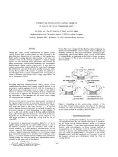
10 Full removal of coatings is universally accomplished by selective dissolution of the coating phase(s) by various simple or complex mixtures of acids. Again, each engine manufacturer, and some Repair houses have more or less independently developed their own acid formulations. Most procedures depend on selective attack of beta (NiAl or CoAl) phases. If the coatings are depleted of the beta phases, selective coating dissolution can become difficult or impossible and residual coatings must then be removed by physical means such as belt grinding. Great care must be exercised in the development and control of stripping solutions in order to avoid localized or general attack of the superalloy base. For example, dilute nitric acid is a commonly used, safe coating strippant. Contamination with a few percent of hydrochloric acid can, however, cause selective attack of the gamma prime (Ni3Al) strengthening phase as illustrated in Figure 1 (15).